What Is an Inductor?
At its heart, an inductor is simply a coil of wire. When current flows through a conductor, it creates a surrounding magnetic field (per Ampere's Law). By coiling the wire, each loop's magnetic field adds together, creating a strong concentrated magnetic flux through the center of the coil.
The key property of an inductor is its opposition to changes in current — described mathematically by Faraday's Law of Electromagnetic Induction. When current tries to increase, the inductor generates a back-EMF (electromotive force) that opposes the increase. When current tries to decrease, it generates a forward EMF to maintain the current flow.
- Inductors store energy in magnetic fields around coil windings.
- Inductor impedance increases proportionally with signal frequency.
- Ferrite cores concentrate magnetic flux and increase inductance per turn.
Faraday's Law & Self-Inductance
The voltage across an inductor is governed by Faraday's Law of Induction:
V = L × (dI / dt)
Where V is the induced voltage in Volts, L is the inductance in Henrys, and dI/dt is the rate of change of current in Amperes per second.
This equation tells us something critical: the faster current tries to change, the larger the opposing voltage. An inductor's self-inductance (L) depends on:
- Number of turns (N²): Inductance scales with the square of the number of turns. Doubling turns quadruples inductance.
- Core permeability (μ): Ferrite cores have high magnetic permeability (μr = 2,000–15,000×), dramatically increasing inductance versus air-core coils.
- Cross-sectional area (A): A wider core concentrates more flux, increasing inductance.
- Core path length (l): Longer magnetic paths reduce inductance — toroidal cores minimize this by having no "air gap" in the flux path.
The RL Circuit Time Constant
When a voltage source is connected to an inductor in series with a resistor (an RL circuit), current doesn't jump instantly to its maximum value — it rises exponentially according to:
I(t) = (V/R) × (1 − e^(−t/τ)) where τ = L/R
The time constant τ = L/R dictates the speed of current rise:
| Time Elapsed | % of Final Current | Status |
|---|---|---|
| 1τ (L/R) | 63.2% | Charging |
| 2τ | 86.5% | Charging |
| 3τ | 95.0% | Charging |
| 5τ | 99.3% | Fully charged |
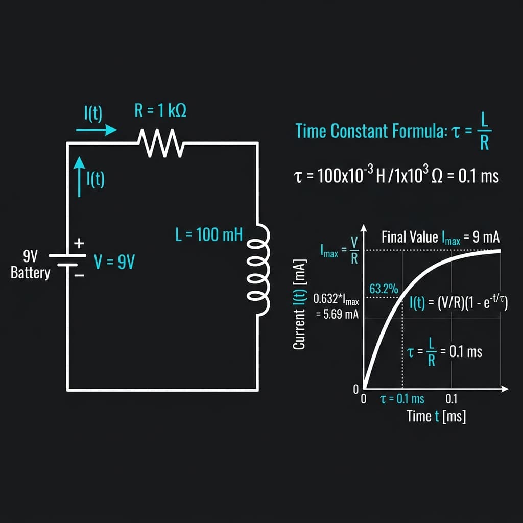
Fig 1: RL circuit current rise — current reaches 63.2% of final value at t=τ=L/R
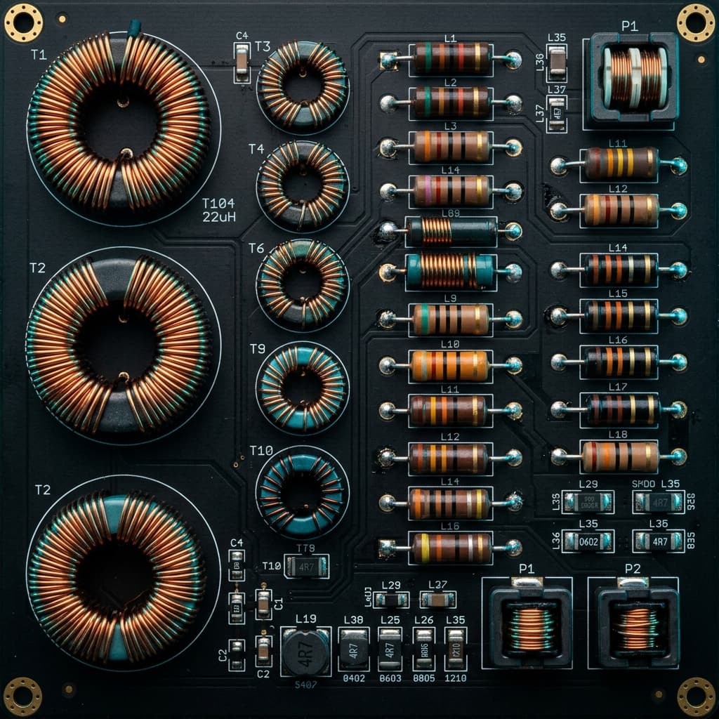
Types of Inductors & Core Materials
The core material used inside an inductor drastically changes its characteristics:
Air Core
No magnetic saturation, very linear, very low inductance. Used in high-frequency RF circuits above 100 MHz.
Ferrite Core
High permeability (μr up to 15,000), excellent for high-frequency switching supplies (20 kHz–2 MHz). Saturates at lower currents.
Iron Powder Core
Lower permeability than ferrite but handles very high DC currents before saturation. Ideal for power inductors in buck/boost converters.
Toroidal Core
Closed magnetic loop = near-zero flux leakage. Self-shielding, lower EMI, higher Q factor. Used in precision audio and power supplies.
Real-World Applications of Inductors
1. DC-DC Switching Converters (Buck & Boost)
Inductors are the heart of switching power regulators. In a buck (step-down) converter, the inductor averages a pulsed high voltage into a smooth lower output. In a boost (step-up) converter, the collapsing magnetic field of the inductor generates a voltage spike higher than the input — your 3.7V LiPo cell powering a 5V USB output is a perfect example.
2. LC Oscillators & Resonant Circuits
Combined with a capacitor, an inductor forms a resonant tank circuit. The resonant frequency is:
f₀ = 1 / (2π × √(L × C))
Used in radio tuners, crystal oscillators, and bandpass filters. The capacitor and inductor exchange energy back and forth — stored alternately as electric field (C) and magnetic field (L).
3. EMI Choke Filters
Power line chokes on USB chargers and mains equipment are inductors designed to block high-frequency switching noise (EMI) from entering the power grid. Since inductive reactance XL = 2πfL scales with frequency, high-frequency noise is blocked while 50/60Hz mains current passes unimpeded.
4. Arduino Project Code: Boost Converter Output Sensing
// Read boost converter output voltage via voltage divider
// R1=10kΩ, R2=3.3kΩ → divide 12V max to 3.3V ADC range
const int voltPin = A0;
const float R1 = 10000.0, R2 = 3300.0;
const float Vref = 5.0;

void setup() { Serial.begin(9600); }

void loop() {
  int raw = analogRead(voltPin);
  float vADC = (raw / 1023.0) * Vref;
  float vBoost = vADC * ((R1 + R2) / R2);
  Serial.print("Boost Output: ");
  Serial.print(vBoost, 2);
  Serial.println(" V");
  delay(500);
}
Frequently Asked Questions
What does an inductor do in a circuit?
An inductor stores energy in a magnetic field when current flows through its coil. It opposes any change in current — resisting a sudden increase and resisting a sudden decrease. This property makes inductors essential for filtering, energy transfer in switching power supplies, and resonant LC circuits.
Why do inductors block high-frequency AC but pass DC?
Inductive reactance XL = 2π × f × L increases proportionally with frequency. At DC (f = 0 Hz), the inductor has zero reactance. At high frequencies, XL becomes very large, blocking AC signals. This is the basis of low-pass EMI filters and choke inductors in power lines.
What is the RL time constant?
The RL time constant τ = L / R defines how quickly current rises in an RL circuit. After one τ, current reaches 63.2% of its final value. After five τ, it is effectively at 99.3% — considered fully charged.
How is an inductor used in a boost converter?
In a boost DC-DC converter, the inductor stores energy when a MOSFET switch is ON. When the switch turns OFF, the collapsing magnetic field forces current through a diode to the output at a higher voltage than the input.
What is the difference between an inductor and a capacitor?
Capacitors store energy in an electric field and oppose voltage changes. Inductors store energy in a magnetic field and oppose current changes. Capacitors pass high-frequency AC and block DC; inductors pass DC and block high-frequency AC.
Conclusion
Inductors are the unsung heroes of power electronics and RF design. From the boost converter in your phone charger to the EMI choke on a motor driver, understanding inductance, RL time constants, and core saturation will unlock your ability to design reliable, efficient circuits.
📚 References & Sources
Related Resources
How Capacitors Work
Understand the capacitor counterpart — electric field energy storage and RC time constants.
How Transistors Work
Learn how MOSFETs switch current in boost converters and PWM circuits.
What Is PWM
Understand the switching signals that drive inductor-based DC-DC converters.
How Power Supplies Work
See how transformers, rectifiers, and filter inductors combine in linear supplies.