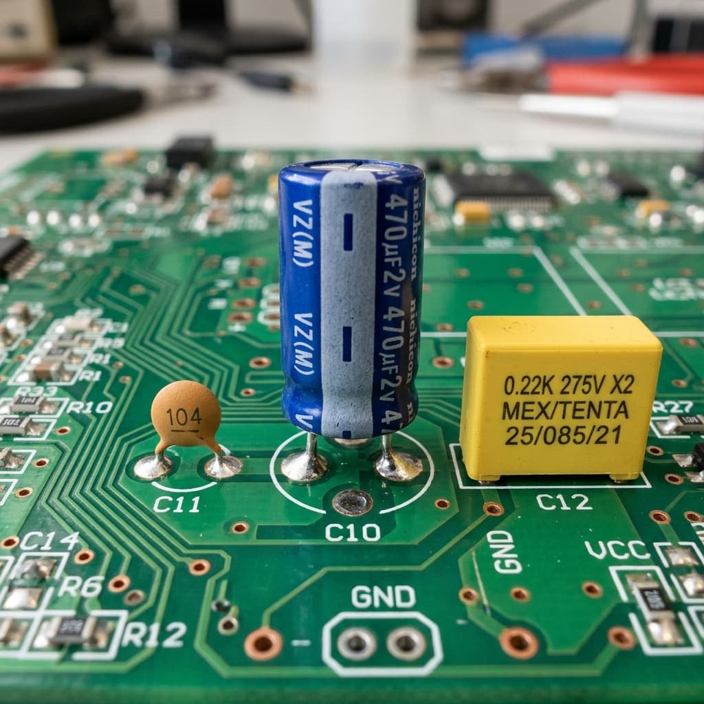
What Is a Capacitor?
A capacitor is a passive electronic component that stores electrical energy in an electric field. Its fundamental structure is two conductive plates separated by an insulating material called a dielectric (air, ceramic, plastic film, or electrolyte). When voltage is applied, opposite charges accumulate on each plate, creating a stored electric field.
Capacitance (measured in Farads, F) defines how much charge can be stored per volt: Q = C × V. Most practical capacitors range from picofarads (pF) to millifarads (mF). Use our Capacitor Charge Calculator to compute charge time and energy storage for any RC circuit.
Charging and Discharging: The RC Time Constant
Capacitors don't charge instantaneously. When connected to a voltage source through a resistor, the charging follows an exponential curve defined by the RC time constant:
τ = R × C
Time Constant (seconds) = Resistance (Ω) × Capacitance (F)
| Time Elapsed | Voltage Charged To | % of Final Voltage |
|---|---|---|
| 1τ (1 × RC) | 3.16V (from 5V) | 63.2% |
| 2τ (2 × RC) | 4.32V | 86.5% |
| 3τ (3 × RC) | 4.75V | 95.0% |
| 4τ (4 × RC) | 4.91V | 98.2% |
| 5τ (5 × RC) | 4.97V | 99.3% (≈ fully charged) |
Capacitor Types: When to Use Which
🔵 Ceramic Capacitor
Range: 1 pF – 100 µF
Polarity: Non-polarized
✅ Pros: Small, cheap, stable, excellent HF performance
❌ Cons: Low capacitance, voltage dependent (Class 2)
Best For: Decoupling, bypass, HF filtering — the 100nF beside every microcontroller
🟤 Electrolytic Capacitor
Range: 1 µF – 100,000 µF
Polarity: Polarized (+ must be connected to higher voltage)
✅ Pros: Very high capacitance, low cost
❌ Cons: Polarized (explodes if reversed!), higher ESR, degrades over time
Best For: Power supply bulk storage, audio coupling, motor drives
🟡 Tantalum Capacitor
Range: 0.1 µF – 1000 µF
Polarity: Polarized
✅ Pros: Compact, stable, low leakage, good HF performance
❌ Cons: Expensive, can fail catastrophically if reversed or overvoltaged
Best For: Portable electronics, medical devices, precision filtering
🟢 Film Capacitor
Range: 1 nF – 100 µF
Polarity: Non-polarized
✅ Pros: Very stable, low ESR, self-healing, excellent for AC
❌ Cons: Larger size, more expensive than ceramic
Best For: Audio crossovers, motor run capacitors, snubber circuits
Series vs Parallel Capacitors
Unlike resistors, capacitors combine in the opposite way — parallel adds capacitance, series reduces it:
Capacitors in Parallel
Capacitance adds up. Voltage rating stays the same. Use to increase total storage or when you need more capacitance than available in a single component.
Capacitors in Series
Capacitance decreases. Voltage rating multiplies. Use to increase voltage handling capability when you only have lower-rated capacitors available.
Key Capacitor Applications in Electronics
- Power Supply Decoupling: 100nF ceramic capacitors placed at each IC power pin absorb switching current spikes, preventing glitches. Every IC datasheet recommends them.
- Bulk Power Supply Filtering: Large electrolytic capacitors (100µF–10,000µF) smooth rectified AC into stable DC in power supplies by storing charge during peaks and releasing it during valleys.
- RC Timing Circuits: In the 555 timer, an external RC network sets the oscillation frequency and pulse width. Longer R or larger C = longer time period.
- AC Coupling (Signal Blocking): Series capacitors block DC while passing AC signals — used in audio amplifiers to connect stages without DC offset coupling.
- Low-Pass/High-Pass Filters: RC filter networks pass or block frequency ranges — critical for audio processing, PWM smoothing, and RF interference rejection.
- Energy Storage (Flash Photography, Defibrillators): Large capacitors store energy and release it as a high-power pulse — the xenon flash in cameras, the discharge in cardiac defibrillators.
Reading Capacitor Values & Markings
Capacitor markings vary by type:
Directly printed: e.g., "100µF 25V" — value in microfarads and voltage rating. Check for the negative stripe (–) indicating the negative lead.
e.g., "104" = 10 × 10⁴ pF = 100,000 pF = 100nF. "103" = 10nF. "472" = 4700 pF. Last digit is the multiplier (number of zeros to add). "Y5V" or "X7R" suffix indicates temperature stability class.
Usually printed in nF or µF directly. May also use 3-digit code like ceramics. Look for voltage rating printed alongside.
Common Capacitor Mistakes to Avoid
❌ Exceeding Voltage Rating
Every capacitor has a maximum voltage rating. Exceeding it causes dielectric breakdown, which permanently destroys the capacitor (and sometimes explosively). Always choose capacitors with a voltage rating 25–50% higher than the maximum circuit voltage.
❌ Placing Decoupling Capacitors Too Far from IC
A decoupling capacitor on the opposite side of the PCB from the IC is nearly useless. The parasitic inductance of long PCB traces defeats the purpose. Place 100nF ceramics within 1–2mm of each power pin.
❌ Ignoring ESR in Power Applications
Equivalent Series Resistance (ESR) causes heating in high-current applications. Standard electrolytic capacitors have high ESR. For switch-mode power supplies and audio amplifiers, use low-ESR capacitors specified for the application.
❌ Using Class 2 Ceramic Capacitors in Precision Circuits
X5R and Y5V ceramic capacitors lose significant capacitance with DC bias voltage and temperature. A 10µF X5R capacitor may effectively be only 2–3µF at rated voltage. Use Class 1 (C0G/NP0) ceramics for precision timing or filtering.
Frequently Asked Questions
What does a capacitor do in a circuit?
A capacitor stores electrical energy in an electric field between two conducting plates. In circuits, capacitors smooth out voltage fluctuations (decoupling), block DC while passing AC signals (coupling), create time delays with resistors (RC timer), filter noise from power lines, and store energy for pulsed discharge applications.
What is the RC time constant?
The RC time constant (τ = R × C) is the time in seconds for a capacitor to charge to 63.2% of the supply voltage through a resistor, or discharge to 36.8% of its initial voltage. After 5 time constants (5τ), the capacitor is considered fully charged or discharged (99.3%). Example: 10kΩ × 100µF = 1 second time constant.
What is the difference between ceramic and electrolytic capacitors?
Ceramic capacitors are small (pF to ~10µF), non-polarized, stable, and excellent for high-frequency decoupling. Electrolytic capacitors are large (1µF to 100,000µF), polarized (must be connected with correct polarity), and best for power supply filtering and energy storage. Never connect an electrolytic capacitor backwards — it will leak, swell, or explode.
Why do I need a decoupling capacitor on a microcontroller?
When a microcontroller switches logic states, it draws sudden bursts of current that cause brief voltage dips on the power supply. A decoupling capacitor (typically 100nF ceramic) placed close to the VCC pin acts as a local charge reservoir, supplying this burst current instantly and preventing the voltage dip from affecting the chip's operation.
Can capacitors in series and parallel be calculated like resistors?
Yes, but the formulas are reversed compared to resistors. Capacitors in parallel add directly: C_total = C1 + C2 + C3. Capacitors in series use the reciprocal formula: 1/C_total = 1/C1 + 1/C2 (like resistors in parallel). Series capacitors divide voltage but reduce total capacitance. Parallel capacitors share voltage but increase total capacitance.
Conclusion
Capacitors are among the most versatile components in electronics. From the humble 100nF ceramic decoupling cap that stabilizes every microcontroller, to the 10,000µF bulk capacitor that smooths your power supply, to the RC network that defines your 555 timer's timing — understanding capacitor behavior unlocks a whole new level of circuit design competence.
Calculate your RC timing with our Capacitor Charge Calculator, design 555 timer circuits with the 555 Timer Calculator, or learn how transistors pair with capacitors in amplifier circuits.
📚 References & Sources
Related Resources
Capacitor Charge Calculator
Calculate charge time, energy stored, and voltage for any RC circuit
555 Timer Calculator
Design timer circuits with the RC time constant
How Transistors Work
Combine transistors with capacitors in amplifier and filter circuits
Ohm's Law Calculator
Calculate RC circuit currents and voltage drops