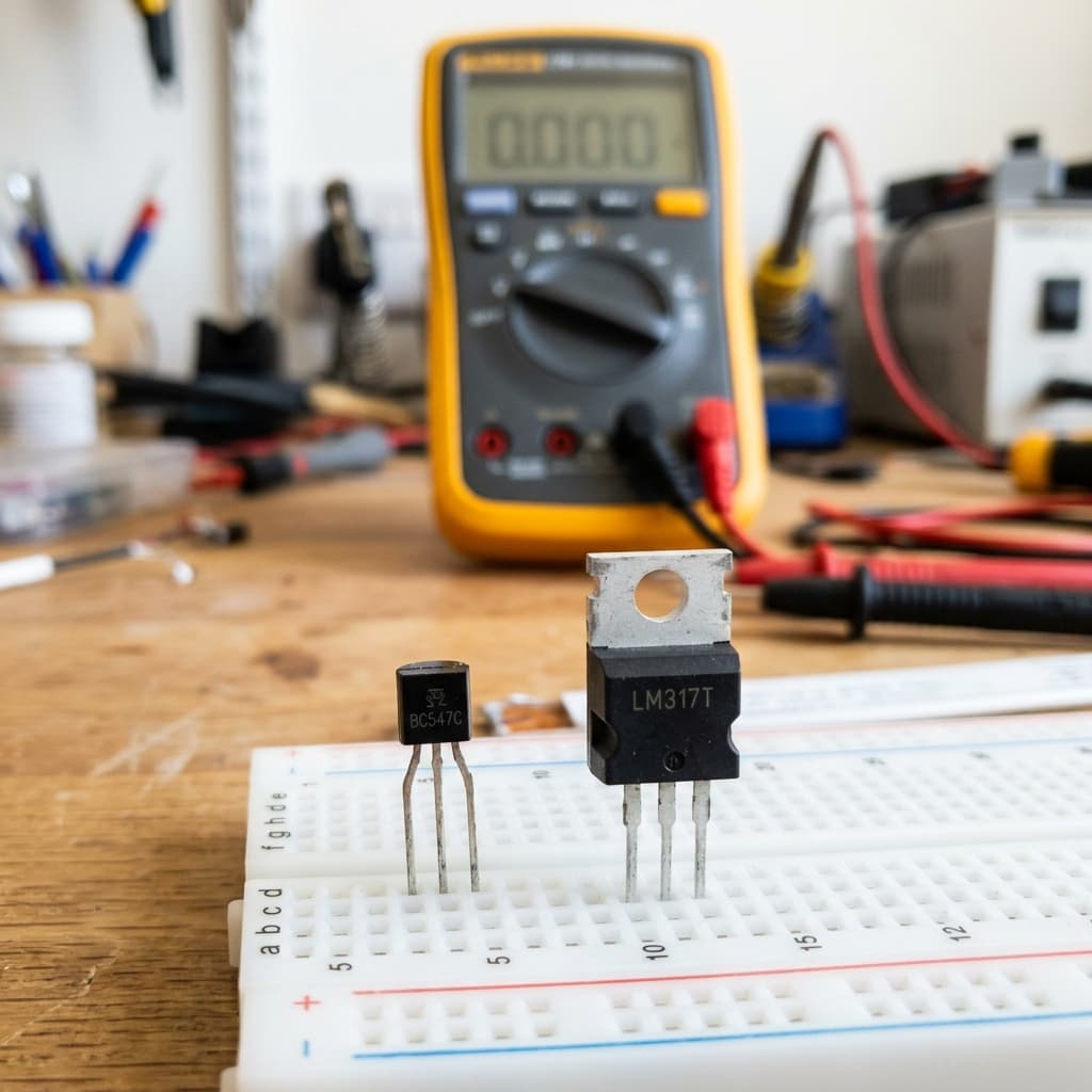
What Is a Transistor?
A transistor is a three-terminal semiconductor device that either amplifies an electrical signal or acts as an electronically controlled switch. Invented in 1947 at Bell Labs, the transistor replaced bulky vacuum tubes and sparked the digital revolution. Today, a single modern CPU contains over 14 billion transistors etched at the 3–5 nanometer scale.
In electronics prototyping — whether you're using an Arduino Uno or an ESP32 — discrete transistors are used to drive motors, control high-current LEDs, interface relays, and build amplifier stages that a microcontroller pin alone cannot handle.
NPN vs PNP: The Two Main BJT Types
Bipolar Junction Transistors (BJTs) come in two polarities defined by their internal semiconductor sandwich:
⚡ NPN Transistor
Structure: N-P-N semiconductor layers. Turns ON when Base voltage is ~0.6V higher than Emitter. Current flows from Collector → Emitter. The most common type — used as a low-side switch. Examples: 2N2222, BC547, 2N3904.
⚡ PNP Transistor
Structure: P-N-P semiconductor layers. Turns ON when Base is pulled ~0.6V below Emitter. Current flows from Emitter → Collector. Used as a high-side switch. Examples: 2N2907, BC557, 2N3906.
How a Transistor Works as a Switch
As a switch, a transistor operates in two states: cutoff (OFF) and saturation (fully ON). This is the operating mode used in digital logic, motor drivers, and relay control circuits.
Three Operating Regions
| Region | Base Bias | Collector Current | Use Case |
|---|---|---|---|
| Cutoff (OFF) | V_BE < 0.6V | ≈ 0 (leakage only) | Digital OFF state |
| Active | V_BE ≈ 0.6–0.7V | IC = hFE × IB | Amplification |
| Saturation (ON) | V_BE > 0.7V (excess IB) | Maximum (load-limited) | Digital switch ON |
Arduino LED/Motor Switch Circuit (NPN)
- Base resistor: Connect a 1kΩ resistor between Arduino digital pin and transistor Base. This limits base current and protects the pin.
- Load connection: Connect your load (motor, LED, relay coil) between VCC (+5V/+12V) and Collector.
- Emitter to GND: Connect Emitter directly to Ground.
- Flyback diode: For inductive loads (motors, relay coils), add a 1N4007 diode across the load in reverse bias to prevent voltage spikes from damaging the transistor.
How a Transistor Amplifies: Current Gain (hFE)
In the active region, a transistor acts as a linear current amplifier. The key parameter is current gain, denoted hFE or β (beta):
IC = hFE × IB
Collector Current = Current Gain × Base Current
A transistor with hFE = 200 amplifies 0.1mA of base current into 20mA of collector current — enough to drive a standard LED directly. Audio amplifiers chain multiple stages to boost tiny microphone signals (microvolts) up to speaker-level power (watts).
Use our Ohm's Law Calculator to compute the base resistor value needed for a target collector current.
BJT vs MOSFET: When to Use Which
MOSFETs (Metal-Oxide-Semiconductor Field-Effect Transistors) are the other major transistor family. Unlike BJTs, they are voltage-controlled — the gate draws virtually no current, making them ideal for high-efficiency switching.
| Feature | BJT | MOSFET |
|---|---|---|
| Control Type | Current-controlled (Base current) | Voltage-controlled (Gate voltage) |
| Input Impedance | Low (kΩ range) | Very High (GΩ range) |
| Switching Speed | Slower (μs) | Very fast (ns) |
| Power Efficiency | Lower (V_CE sat ~0.2V) | Higher (R_DS(on) < 10mΩ) |
| Gate Drive | Requires base current | No gate current needed |
| Best For | Linear amplification, audio | PWM, motor drivers, power supplies |
| Common Examples | 2N2222, BC547, TIP31 | IRF540, IRLZ44N, 2N7000 |
Common Transistor Mistakes to Avoid
❌ Wrong Pinout
Transistor pin order (Base, Collector, Emitter) varies by package. ALWAYS check the datasheet — a 2N2222 in TO-18 package has a different pinout than in TO-92. Getting it wrong destroys the transistor instantly.
❌ No Base Resistor
Connecting Base directly to a GPIO pin allows excessive current that burns the pin and transistor. Always use a resistor (typically 1kΩ–10kΩ) to limit base current.
❌ No Flyback Diode on Inductive Loads
Motors and relay coils generate reverse voltage spikes when switched off. Without a flyback diode (1N4007) across the load, this spike can exceed 100V and destroy the transistor.
❌ Using Non-Logic-Level MOSFET with 3.3V MCU
Standard MOSFETs (like IRF540) need 10V+ gate drive to fully turn on. With a 3.3V Arduino or ESP32, use a "logic-level" MOSFET (like IRLZ44N) specified to fully conduct at 3.3V–5V gate voltage.
Frequently Asked Questions
What is a transistor and what does it do?
A transistor is a semiconductor device that can amplify electrical signals or act as an electronic switch. It has three terminals (Base, Collector, Emitter for BJTs; Gate, Drain, Source for MOSFETs) and controls a large current flow using a small input signal. Transistors are the fundamental building blocks of all modern electronics.
What is the difference between NPN and PNP transistors?
In an NPN transistor, current flows from Collector to Emitter when a positive voltage is applied to the Base — it turns ON with a HIGH signal. In a PNP transistor, current flows from Emitter to Collector when the Base is pulled LOW (negative relative to Emitter) — it turns ON with a LOW signal. NPN transistors are more common and easier to use in most circuits.
What is the difference between a BJT and a MOSFET?
A BJT (Bipolar Junction Transistor) is current-controlled — a small base current controls a larger collector current. A MOSFET is voltage-controlled — a voltage on the gate controls drain-source current without drawing gate current. MOSFETs are faster, more power-efficient, and better for high-frequency switching. BJTs are simpler to bias and better for linear amplification.
How do you use a transistor as a switch with Arduino?
Connect a 1kΩ resistor between the Arduino digital output pin and the transistor Base. Connect the Emitter to GND. Connect your load (LED, motor, relay) between VCC and the Collector. When the Arduino pin goes HIGH (5V), base current flows, saturating the transistor and switching the load ON. When the pin goes LOW, the transistor cuts off and the load turns OFF.
What is transistor current gain (hFE or beta)?
Current gain (hFE or β) is the ratio of collector current to base current: hFE = IC / IB. A transistor with hFE = 100 means 1mA of base current controls 100mA of collector current. Typical small-signal transistors have hFE between 100–300. To ensure saturation (fully ON state), drive the base with more current than IC/hFE — usually add a safety factor of 10x.
Conclusion
Transistors are the invisible engines of the modern world — every phone call, video stream, and Arduino sketch depends on billions of them switching billions of times per second. Whether you need a simple NPN switch for a relay module or an N-channel MOSFET for a motor driver, understanding the three operating regions and choosing the right device will make your circuits reliable and efficient.
Ready to put transistors to work? Explore our Arduino Uno guide, calculate resistor values with the Ohm's Law Calculator, or dive into PWM with transistors for motor speed control.
📚 References & Sources
Related Resources
What Is PWM?
Use transistors & MOSFETs to generate PWM for motor and LED control
Ohm's Law Calculator
Calculate base resistor values for your transistor switch circuits
Arduino Uno Guide
Drive relays, motors, and LEDs with transistor-based Arduino circuits
How Capacitors Work
Pair capacitors with transistors for filters and timing circuits