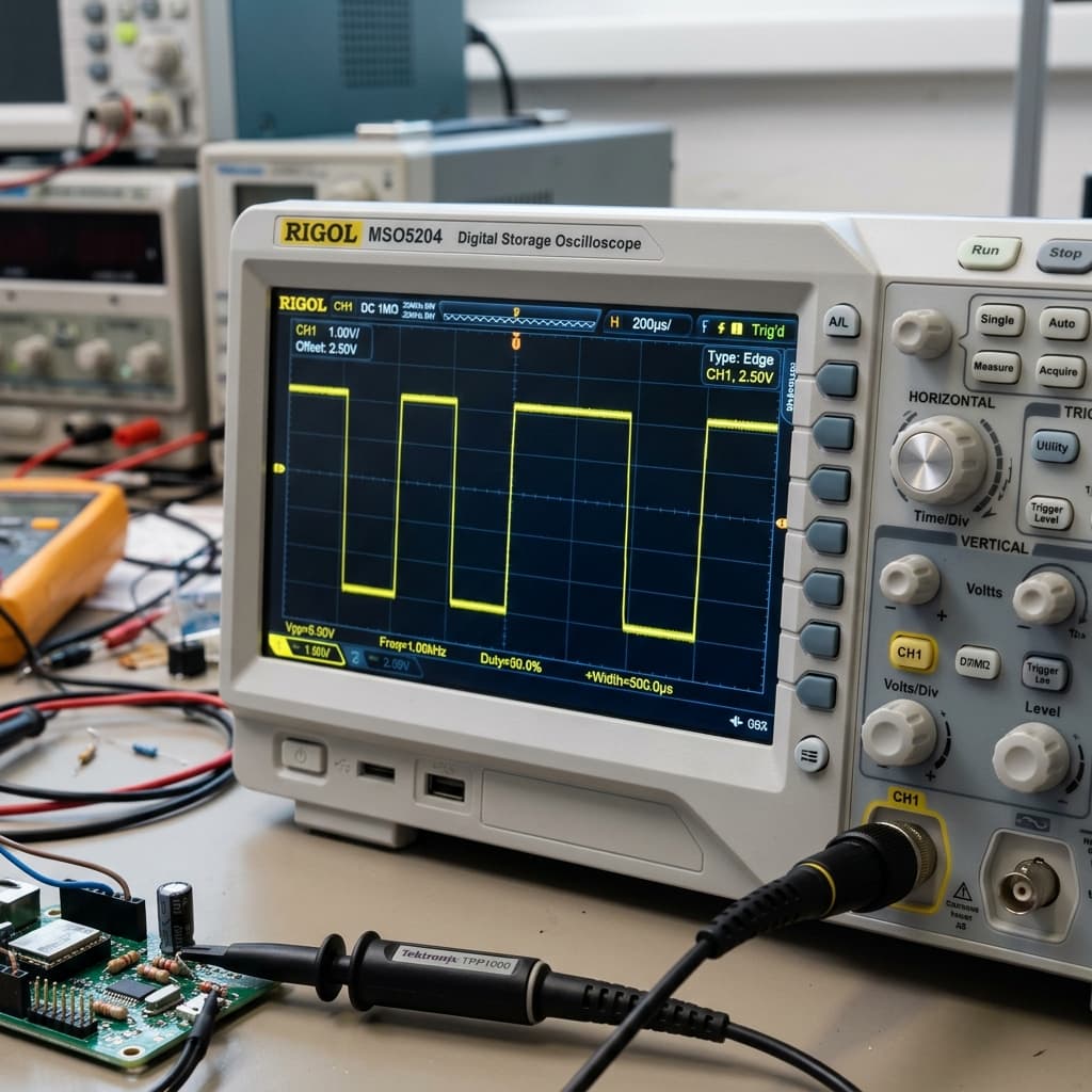
What Is PWM?
Pulse Width Modulation (PWM) is a digital technique that controls the amount of power delivered to a component by rapidly switching a signal between HIGH and LOW. Rather than producing a true analog voltage, PWM creates an average effective voltage by varying the ratio of ON time to OFF time within each cycle.
Microcontrollers like the Arduino Uno are fundamentally digital devices — their output pins can only be fully ON (5V) or fully OFF (0V). PWM bridges this gap, allowing digital hardware to control analog-feeling behaviors like smooth LED fades and precise motor speeds.
Duty Cycle: The Heart of PWM
The duty cycle is the percentage of one PWM period during which the signal is HIGH. It directly determines the average voltage delivered:
V_avg = Duty Cycle (%) × V_supply
Example: 50% × 5V = 2.5V average output
| Duty Cycle | analogWrite Value (Arduino) | Avg Voltage (5V supply) | Effect on LED |
|---|---|---|---|
| 0% | 0 | 0V | Off |
| 25% | 64 | 1.25V | 25% brightness |
| 50% | 128 | 2.5V | 50% brightness |
| 75% | 191 | 3.75V | 75% brightness |
| 100% | 255 | 5V | Full brightness |
PWM Frequency: Why It Matters
PWM frequency defines how many ON/OFF cycles occur per second (measured in Hz). Frequency and duty cycle are independent: frequency sets how fast you switch, duty cycle sets how long you stay ON.
🔆 LED Dimming
1 kHz – 100 kHz
Above 100 Hz eliminates visible flicker. Higher frequencies (10 kHz+) prevent any eye strain.
⚙️ DC Motor Control
5 kHz – 50 kHz
Higher frequencies eliminate audible motor whine (above human hearing threshold of 20 kHz).
🤖 Servo Motors
Exactly 50 Hz
Servos expect a 50 Hz signal with pulse width 1–2ms to define position angle.
🔊 Audio Generation (DAC)
44.1 kHz+
PWM at very high frequency with filtered output produces audio signals from digital data.
Generating PWM with Arduino
Arduino's analogWrite(pin, value) function generates PWM on hardware-designated PWM pins (marked with ~ on the board).
LED Fading Example
// Fade LED on PWM pin 9
void setup() { pinMode(9, OUTPUT); }
void loop() {
for (int i = 0; i <= 255; i++) {
analogWrite(9, i); // Increase brightness
delay(10);
}
}
Servo Motor Control
Servo motors use a special form of PWM where the pulse width (not duty cycle percentage) determines the servo angle. A 1ms pulse = 0°, 1.5ms = 90°, 2ms = 180°. The signal repeats at 50 Hz (every 20ms). Use the Servo Motor Guide and our PWM Calculator to compute exact pulse values.
Real-World PWM Applications
- LED Dimming: Every smart bulb and RGB strip uses PWM to create thousands of brightness levels from a purely digital signal.
- DC Motor Speed Control: PWM through an H-bridge (like L298N or DRV8833) allows bidirectional, variable-speed motor control without resistive power loss.
- Servo Positioning: RC hobby servos, robotics joints, and camera gimbals all use PWM pulse-width encoding to hold precise angles.
- Switch-Mode Power Supplies (SMPS): Modern chargers and voltage regulators use high-frequency PWM (100 kHz+) through inductors and capacitors to convert voltages efficiently.
- Audio (Class-D Amplifiers): Class-D amplifiers convert audio signals to PWM, switch transistors at 500 kHz+, then low-pass filter back to audio — achieving 90%+ efficiency vs 50% for Class-A/B.
- Fan Speed Control: PC CPU fans use 4-pin PWM at 25 kHz to silently adjust speed based on temperature.
Common PWM Mistakes to Avoid
❌ Using Non-PWM Pins with analogWrite()
analogWrite() only works on PWM pins (~). Calling it on a regular digital pin produces unexpected behavior. Always check pin numbers — Arduino Uno PWM pins are 3, 5, 6, 9, 10, 11.
❌ Wrong Frequency for Servos
Servos require exactly 50 Hz with pulse widths of 1–2ms. Using analogWrite() directly is unreliable for servos — always use the Arduino Servo library which handles timing correctly.
❌ PWM Frequency Too Low for Motors
Very low PWM frequencies (below 1 kHz) cause audible whining and inefficient motor operation. If you hear a buzzing sound from your motor, increase the PWM frequency using timer registers or a dedicated motor driver IC.
❌ No Low-Pass Filter for Analog Output
PWM is not a true analog signal. Connecting PWM directly to analog sensors or audio circuits without an RC low-pass filter will introduce noise. Filter with a 10kΩ resistor and 1μF capacitor to get a smooth DC voltage.
Frequently Asked Questions
What is PWM and how does it work?
PWM (Pulse Width Modulation) is a technique where a digital signal rapidly switches between HIGH and LOW states. By varying the proportion of time spent HIGH (duty cycle), PWM simulates an analog voltage. A 50% duty cycle at 5V produces an effective average of 2.5V. The signal switches so fast that components like LEDs and motors respond to the average power, not the individual pulses.
What is duty cycle in PWM?
Duty cycle is the percentage of one period in which the PWM signal is HIGH (ON). A 25% duty cycle means the signal is HIGH for 25% of each cycle and LOW for 75%. Duty cycle directly controls the effective power delivered: a 25% duty cycle at 5V delivers 1.25V average, 50% delivers 2.5V, and 100% delivers full 5V.
How do I use PWM on Arduino?
Use the analogWrite(pin, value) function on Arduino PWM pins (marked with ~ on the board). The value ranges from 0 (0% duty cycle) to 255 (100% duty cycle). For example, analogWrite(9, 128) sets approximately 50% duty cycle on pin 9. Arduino Uno PWM pins are 3, 5, 6, 9, 10, and 11.
What is PWM frequency and why does it matter?
PWM frequency is how many times per second the signal completes one ON/OFF cycle. Higher frequency produces smoother control and less audible noise in motors. Arduino Uno uses 490 Hz on most PWM pins (980 Hz on pins 5 and 6). For motor control, 20–50 kHz is common to eliminate audible whining. For servo motors, exactly 50 Hz is required.
Can PWM damage motors or LEDs?
PWM is generally safe for motors and LEDs when used correctly. For motors, too-low PWM frequency (below 1 kHz) can cause cogging and inefficient operation — aim for 20 kHz+. For LEDs, PWM frequencies below 100 Hz may cause visible flickering. PWM at 1 kHz+ is invisible to the human eye. Always ensure your PWM current does not exceed the component's rated current.
Conclusion
PWM is one of the most versatile tools in embedded electronics. By mastering duty cycle and frequency, you unlock smooth LED fades, precise motor control, servo positioning, and efficient power conversion — all from a digital output pin. Whether you're building a robot, a smart light controller, or an audio synthesizer, PWM is the bridge between the digital and analog worlds.
Try our PWM Calculator to compute duty cycles, explore servo motor control, or check out transistors and MOSFETs for driving high-power PWM loads.