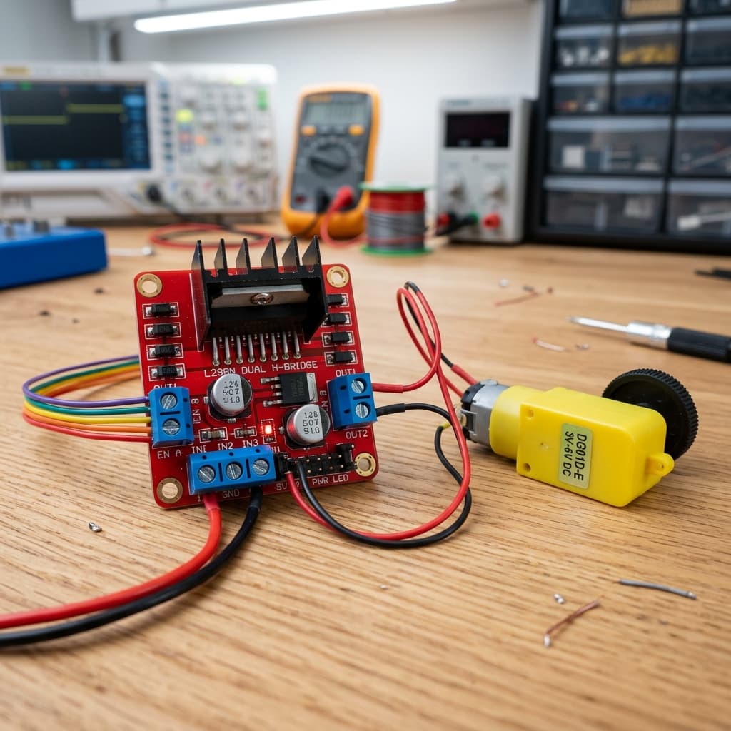
What is an H-Bridge?
A DC motor rotates clockwise or counter-clockwise depending on the polarity of the voltage applied to its two terminals. If you swap the positive and negative connections, the motor reverses direction. In a physical circuit, you cannot manually swap wires at kilohertz speeds — so we use an H-bridge.
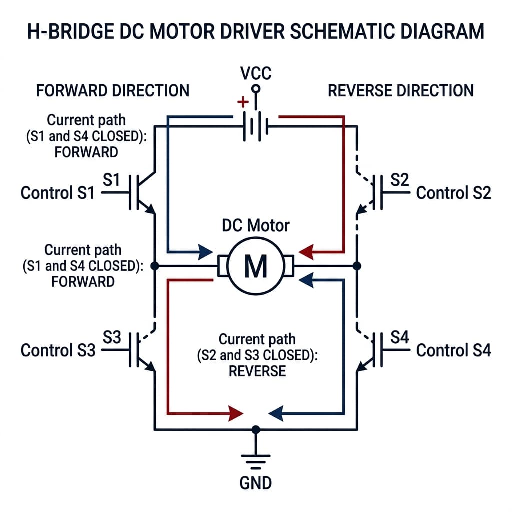
An H-bridge is an electronic circuit consisting of four switches arranged in an "H" topology, with the motor positioned in the center crossbar. By closing specific pairs of switches, we can steer current through the motor in either direction from a single, static DC power source.
- H-Bridge switches direct electrical current paths.
- Polarity reversals control DC motor rotation directions.
- Transistor switches direct voltage configurations.
The Four H-Bridge Switch States
To control the motor safely and correctly, the switches in the H-bridge (which are physically transistors like BJTs or MOSFETs) are activated in specific combinations:
| State | Closed Switches | Current Direction | Motor Behavior |
|---|---|---|---|
| Forward | S1 & S4 | Left to Right (A ➔ B) | Spins Forward (Clockwise) |
| Reverse | S2 & S3 | Right to Left (B ➔ A) | Spins Reverse (Counter-Clockwise) |
| Brake (Short) | S3 & S4 (or S1 & S2) | Terminals shorted together | Quick stop (Dynamic braking) |
| Coast (Open) | None | Zero current (disconnected) | Slowly glides to a stop |
L298N vs Modern MOSFET H-Bridges
In consumer robotics modules, you will often find two major families of H-bridges: BJT-based (like the vintage L298N) and MOSFET-based (like the modern TB6612FNG or DRV8833).
The L298N is a classic BJT dual H-bridge. However, it is highly inefficient by modern standards because of its bipolar junction transistor structure. BJT saturation voltage drop (V_CE(sat)) causes a **1.5V to 3V drop** across the IC. If you connect a 6V battery to an L298N, your motor may only receive 3.5V, and the lost energy is released as heat, requiring a bulky metal heat sink.
Modern MOSFET H-bridges have extremely low Drain-Source On-Resistance (R_DS(on), often under 100mΩ). Because of this, the voltage drop is negligible, the chip remains cool, and battery efficiency is drastically improved, making them far superior for mobile robotic chassis.
Speed Control Using PWM
While the H-bridge switches direction by closing diagonal pairs, it controls **speed** using Pulse Width Modulation (PWM).
By rapidly turning the active high-side switch (S1 or S2) ON and OFF thousands of times per second (usually at 1kHz to 20kHz), the average voltage applied to the motor winding is varied proportional to the duty cycle. For instance, at a 75% duty cycle on a 12V motor, the motor acts as an integrator, averaging the pulses to spin at approximately 75% of its top speed.
Inductive Spikes & Flyback Diodes
A DC motor is an inductive load made of wire coils. Inductors resist sudden changes in electric current. When you open a closed switch in an H-bridge to turn the motor off, the magnetic field in the motor coil collapses, creating a massive high-voltage reverse spike (called Back-EMF or kickback).
To prevent this voltage spike (which can easily exceed 100V) from breaching and frying the transistors in the H-bridge, **flyback diodes** must be placed in reverse bias across each of the four switches. These diodes provide a safe recirculation pathway for the decaying current until it dissipates. Integrated chips (like the L293D and TB6612) contain these diodes internally, whereas raw L298N boards include them as external components.
Practical Arduino Wiring with L298N
To control a motor with an Arduino Uno, connect three pins: two digital direction pins (e.g., IN1, IN2) and one PWM-capable speed pin connected to Enable A (ENA).
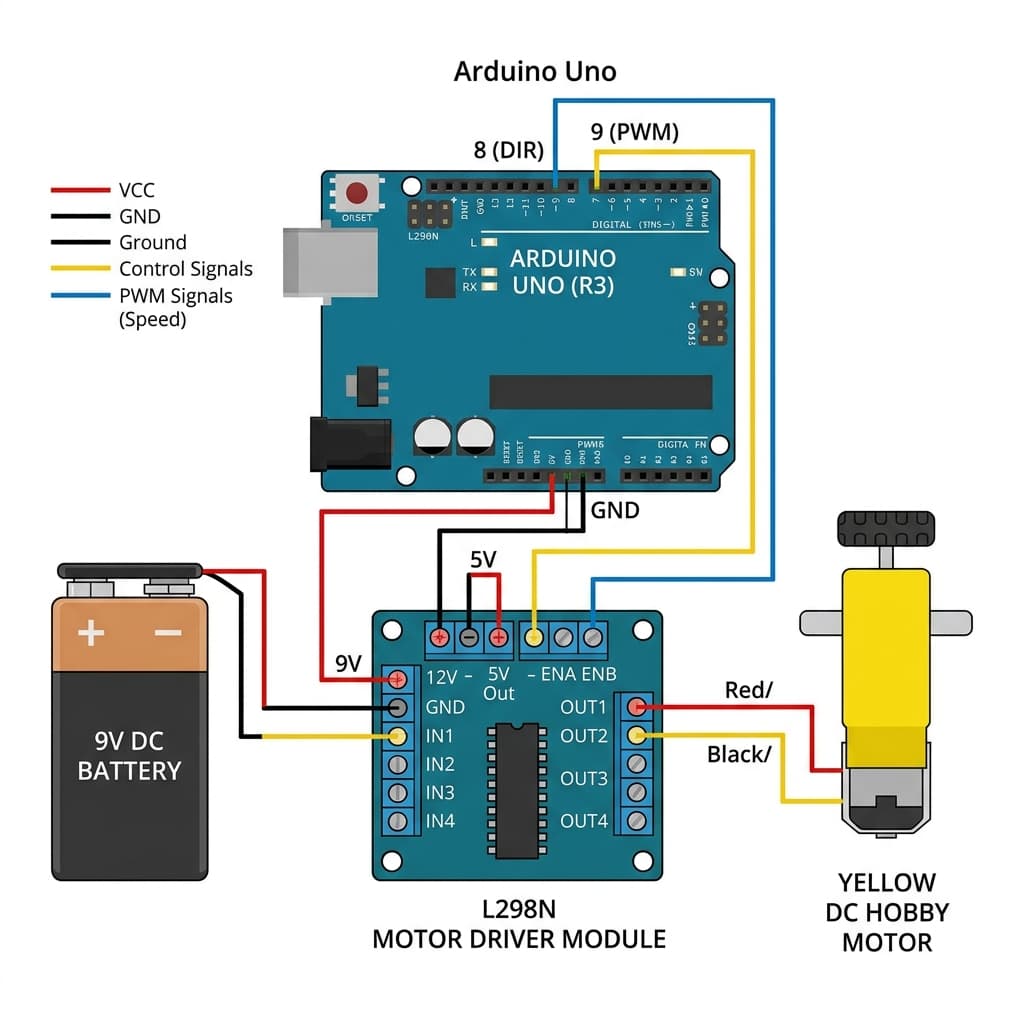
**Basic Arduino Control Code Example:**
// Pin Definitions
const int ENA = 9;  // PWM pin for speed control
const int IN1 = 8;  // Direction Pin 1
const int IN2 = 7;  // Direction Pin 2

void setup() {
  pinMode(ENA, OUTPUT);
  pinMode(IN1, OUTPUT);
  pinMode(IN2, OUTPUT);
}

void loop() {
  // Move Forward at 75% speed (191 out of 255)
  digitalWrite(IN1, HIGH);
  digitalWrite(IN2, LOW);
  analogWrite(ENA, 191);
  delay(3000);

  // Hard Brake
  digitalWrite(IN1, HIGH);
  digitalWrite(IN2, HIGH);
  delay(1000);

  // Move Reverse at 50% speed (127 out of 255)
  digitalWrite(IN1, LOW);
  digitalWrite(IN2, HIGH);
  analogWrite(ENA, 127);
  delay(3000);

  // Coast Stop
  digitalWrite(IN1, LOW);
  digitalWrite(IN2, LOW);
  analogWrite(ENA, 0);
  delay(2000);
}
Robotics Hardware & H-Bridge Component Availability in India
Whether you are a student, hobbyist, or engineering professional, sourcing high-quality motor driver boards like the L298N, TB6612FNG, or DRV8833 is highly convenient across major technology hubs in India. You can easily find these components at local electronics markets and leading online stores:
Mumbai
Purchase directly at Lamington Road, South Mumbai's ultimate electronics wholesale market. Excellent for instant component testing and bulk deals.
Delhi
Visit Lajpat Rai Market near Chandni Chowk, North India's largest semiconductor and electronics hub. Great for custom robotics chassis.
Bangalore
Head to SP Road (Sadashivarudraiah Road) for premium developer modules. Bangalore is the electronics capital, offering cutting-edge components.
Hyderabad
Shop at Gujarati Gali in Koti, Hyderabad's prime marketplace for electronics components, microcontrollers, and DIY robotics boards.
Pune
Sourced from local engineering hubs around Budhwar Peth and online express deliveries catering directly to university tech projects.
Chennai
Explore Ritchie Street in Mount Road, the premier IT and hardware market in Tamil Nadu. Ideal for standard L298N dual H-bridge modules.
Kolkata
Visit Chandni Chowk Market for cheap, reliable robotics components, gear motors, breadboards, and basic driver units.
Frequently Asked Questions
What is an H-bridge and why is it used?
An H-bridge is an electronic circuit configured in an "H" shape containing four switches (transistors) with a load (DC motor) in the center. It is used in robotics and power electronics to reverse the polarity of the voltage applied to a motor, allowing it to spin both clockwise (Forward) and counter-clockwise (Reverse) from a single DC power source.
What is the difference between braking and coasting in an H-bridge?
In the Coasting state, all four switches in the H-bridge are turned OFF, disconnecting the motor from power and allowing it to spin freely to a stop. In the Braking state, both low-side switches (or both high-side switches) are closed while the others are open. This shorts the motor terminals together, forcing the back-EMF generated by the spinning rotor to create a resisting magnetic torque, bringing the motor to a sudden, controlled halt.
Why should you avoid using an L298N driver for low-voltage motors?
The L298N is an older BJT-based driver that exhibits a high internal saturation voltage drop (Vce sat) of about 1.5V to 3V. For example, if you supply 5V to the driver, the motor will only receive 2V to 3.5V, with the remaining energy dissipated as heat. Modern MOSFET-based drivers like the TB6612FNG or DRV8833 have extremely low internal resistance, suffering almost zero voltage drop, making them far better for low-voltage battery-powered projects.
How does an H-bridge control motor speed with PWM?
Speed control is achieved by rapidly switching the high-side or enable switches ON and OFF using a Pulse Width Modulation (PWM) signal. By varying the Duty Cycle (the ratio of ON time to total time), the average voltage applied to the motor is adjusted. For example, a 50% PWM duty cycle on a 12V supply effectively delivers a 6V average, spinning the motor at half speed.
What is "shoot-through" in an H-bridge and how is it prevented?
Shoot-through occurs when both the top and bottom transistors on the same half-bridge are switched ON simultaneously. This creates a direct short-circuit between VCC and GND, causing huge current spikes, severe overheating, and permanent component failure. Modern motor driver ICs include hardware-level "dead-time" protection delays to ensure one transistor is completely cut off before its opposite counterpart turns on.
Conclusion
The H-bridge is a fundamental building block of physical computing, bridge topologies, and high-power electronic drive systems. Understanding how to manage the four operating states, selecting modern MOSFET ICs over obsolete BJT L298N drivers, and using PWM for speed control will empower you to design powerful, efficient robotic drivetrains and motor controllers.
Ready to control actuators? Pair your H-bridge with the Arduino Uno, dive deeper into the physics of Pulse Width Modulation, or protect your circuits using discrete MOSFET switches.
📚 References & Sources
Related Resources
What Is PWM?
Control H-bridge speed and duty cycles with rapid pulse-width modulation.
Arduino Uno Guide
Learn basic digital input/output, timing, and motor control.
How Transistors Work
Learn BJT and MOSFET physics — the building blocks of an H-bridge.
How Capacitors Work
Filter inductive noise and supply spikes from high-power DC motor drivers.