Understanding Commutation in Brushless Motors
Unlike brushed DC motors which use mechanical copper brushes and split-ring commutators to reverse the current direction, brushless DC (BLDC) motors perform commutation electronically. The stator windings must be energized sequentially based on the physical position of the permanent magnets on the rotor.
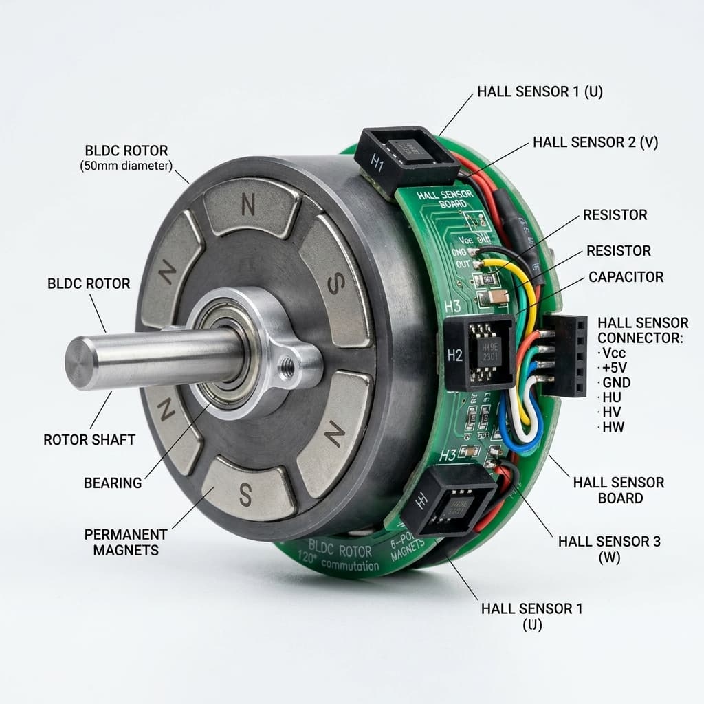
To know when to energize which phase winding, the Electronic Speed Controller (ESC) needs continuous feedback indicating where the rotor magnets are positioned. This feedback is supplied by three latching Hall effect sensors embedded directly inside the motor.
- Latching sensors track permanent rotor magnets.
- Commutation electronics energize stator windings.
- Magnetic phase angles trigger motor state steps.
Why Latching Sensors are Mandatory
A standard latching Hall sensor (such as the US1881) exhibits a memory-like switching operation. When exposed to a South magnetic pole, the sensor turns ON and outputs a LOW electrical state. It remains in this state even if the South pole is removed. The sensor will only turn OFF (output HIGH) when exposed to an opposite North magnetic pole.
This latching action is critical for BLDC commutation because the rotor is surrounded by alternating North and South permanent magnet segments. As the rotor rotates:
- A South pole passes, latching the output LOW.
- The gap between poles passes, but the sensor remains LOW.
- A North pole passes, unlatching the output to HIGH.
This yields a highly reliable, noise-tolerant square wave output with a 50% duty cycle, matching the motor speed and rotor alignment.
6-Step Commutation & Spacing
Most sensored BLDC motors place three Hall sensors at either 120 electrical degrees or 60 electrical degrees apart. In a 120-degree setup, the outputs of the three sensors (H1, H2, H3) never display all zeros (0-0-0) or all ones (1-1-1). This provides 6 distinct states per electrical revolution:
| Step | H1 Output | H2 Output | H3 Output | Phase A | Phase B | Phase C |
|---|---|---|---|---|---|---|
| 1 | 1 | 0 | 1 | HIGH | LOW | NC (Floating) |
| 2 | 1 | 0 | 0 | HIGH | NC (Floating) | LOW |
| 3 | 1 | 1 | 0 | NC (Floating) | HIGH | LOW |
| 4 | 0 | 1 | 0 | LOW | HIGH | NC (Floating) |
| 5 | 0 | 1 | 1 | LOW | NC (Floating) | HIGH |
| 6 | 0 | 0 | 1 | NC (Floating) | LOW | HIGH |
By mapping these 6 digital sensor states directly to switching states in a 3-phase MOSFET bridge (H-Bridge array), the ESC maintains continuous, efficient rotation.
Arduino Speed Tracking from BLDC Hall Signals
In addition to commutation, you can use the pulses from one or all three Hall sensors to calculate motor speed. Connect the Hall signal output to an interrupt-enabled pin on a microcontroller.
// Arduino Uno BLDC Hall Speed Sensor Reader
const int HALL_A_PIN = 2; // Interrupt Pin 0
volatile unsigned long pulseCount = 0;
unsigned long lastTime = 0;
const float polePairs = 4.0; // Number of rotor pole-pairs

void IRAM_ATTR countPulse() {
  pulseCount++;
}

void setup() {
  Serial.begin(115200);
  pinMode(HALL_A_PIN, INPUT_PULLUP);
  attachInterrupt(digitalPinToInterrupt(HALL_A_PIN), countPulse, RISING);
}

void loop() {
  unsigned long currentTime = millis();
  if (currentTime - lastTime >= 1000) { // Update once per second
    noInterrupts();
    unsigned long pulses = pulseCount;
    pulseCount = 0;
    interrupts();

    // RPM = (pulses / polePairs) * 60 seconds
    float rpm = (float(pulses) / polePairs) * 60.0;

    Serial.print("Rotor Speed: ");
    Serial.print(rpm);
    Serial.println(" RPM");

    lastTime = currentTime;
  }
}
Latching Hall Sensors & BLDC Commutators Sourcing in India
Latching Hall sensors like the US1881, Honeywell SS41F, and Allegro A1220 are readily available at retail and wholesale electronic markets in India for motor encoders and custom ESC building:
Mumbai
Purchase latching Hall switches (US1881) at Lamington Road distributors and wholesale component shops.
Delhi
Find motor sensor PCB replacements and 120-degree Hall sensor assemblies in Lajpat Rai Market (Chandni Chowk).
Bangalore
Sourcing industrial SS41F high-temp latching sensors is fast at SP Road electronics shops and online Indian portals.
Hyderabad
Koti's Gujarati Gali shops stock standard 3-pin TO-92 latching sensors and pre-assembled BLDC speed encoders.
Pune
Buy digital speed feedback sensor modules from engineering shops in Budhwar Peth.
Chennai
Ritchie Street carries unipolar and latching sensor ICs, plus ESC testing boards and microcontrollers.
Kolkata
Visit Chandni Chowk vendors for cheap US1881 ICs, 10k resistors, and BLDC replacement boards.
Frequently Asked Questions
Why do BLDC motors require latching Hall effect sensors instead of unipolar switches?
Latching Hall sensors are required because they respond to magnetic pole transitions. A latching sensor turns ON (LOW) when exposed to a South pole and remains in that state even when the pole passes. It will only turn OFF (HIGH) when exposed to a North pole. This toggle action perfectly mirrors the alternating North and South permanent magnets on the BLDC motor rotor, producing a stable 50% duty cycle square wave representing rotor position.
What is the difference between 120-degree and 60-degree sensor spacing in BLDC motors?
The difference refers to the electrical phase spacing between the outputs of the three Hall sensors. In a 120-degree configuration, the active commutation states are offset by 120 electrical degrees, meaning the sensor outputs never read all 0s or all 1s (invalid states). In a 60-degree layout, the sensors are placed closer together, leading to invalid states of 1-1-1 and 0-0-0. ESC controllers must be configured specifically for the motor's physical sensor angle to perform correct 6-step switching.
How do you test if a BLDC motor Hall sensor is working correctly?
To test a Hall sensor, supply 5V DC to the sensor VCC and GND pins. Connect a 10kΩ pull-up resistor between the signal output pin and VCC. Use a multimeter to measure the voltage between the signal pin and GND. Slowly rotate the motor shaft by hand. If the sensor is functioning, you will see the output voltage toggle cleanly between 5V (logic High) and 0V (logic Low) as the rotor magnets pass the sensor.
What is trapezoidal 6-step commutation?
Trapezoidal 6-step commutation is a method of driving BLDC motors where the rotation of the rotor is divided into six distinct electrical steps. In each step, one phase winding is energized with current positive, one is energized with current negative, and the third winding is left open. The state changes are triggered precisely by the rising or falling edges of the three latching Hall effect sensors.
Can you run a BLDC motor without Hall sensors?
Yes, this is known as sensorless BLDC control. Instead of Hall sensors, the controller monitors the Back Electromotive Force (Back-EMF) induced in the inactive motor phase winding to detect rotor position. However, because Back-EMF is zero when the motor is stopped, sensorless control suffers from poor starting torque and rough low-speed operation, making sensored motors superior for high-torque startups and robotics.
Conclusion
Latching Hall effect sensors form the backbone of modern sensored motor control, linking physical rotation with digital electronic commutators. Understanding their binary memory properties, the 6-step commutation matrix, and standard microprocessor timing techniques allows you to design highly efficient motor drivers and positioning loops.
Ready to go deeper? Interface your speed encoders with the PID feedback loop guide, explore phase switching using the H-Bridge motor driver breakdown, or read sensor waveforms in the General Hall Effect overview.
📚 References & Sources
Related Resources
Field Oriented Control (FOC) Guide
Learn vector control for premium BLDC positioning and torque management.
How H-Bridges Work
Analyze how switching matrices change currents across motor phase winding.
How PID Controllers Work
Implement closed-loop RPM regulation using Hall sensor pulse counters.
How Hall Effect Sensors Work
Revisit the fundamentals of Lorentz force and Hall voltage.