The Physics Behind the Hall Effect
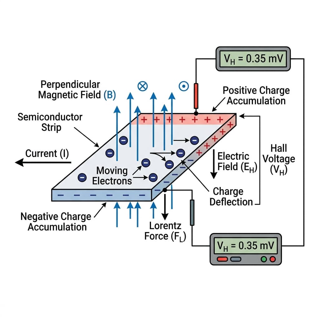
To understand Hall effect sensors, we must look at the underlying electromagnetic physics. Discovered by physicist Edwin Hall in 1879, the **Hall Effect** refers to the accumulation of charge carriers on one side of a current-carrying conductor when exposed to a magnetic field.
When a flat conductor carries electrical current, electrons flow in a straight line. If you introduce a magnetic field perpendicular to the direction of this current, the moving electrons experience a transverse force called the Lorentz Force.
- Lorentz force deflects moving electrical charges.
- Magnetic fields build up charge potentials.
- Hall effect sensors generate transverse voltage signals.
This force pushes electrons to one edge of the conductor. As electrons accumulate on one side, an electric potential difference (voltage) builds up between the left and right edges. This voltage is called the **Hall Voltage ($V_H$)**. The magnitude of $V_H$ is directly proportional to the strength of the magnetic field, providing a direct metric to measure magnetic force.
Linear, Switching, and Latching Sensors
Silicon-based Hall effect sensors amplify the tiny microvolt-level Hall voltage internally. Depending on the internal processing circuitry, they are classified into three major device families:
📈 Linear (Analog)
Outputs a continuous analog voltage proportional to the magnetic field strength. Useful for absolute distance tracking, compasses, and magnetic current sensors. Example: SS49E.
🔌 Unipolar Switch
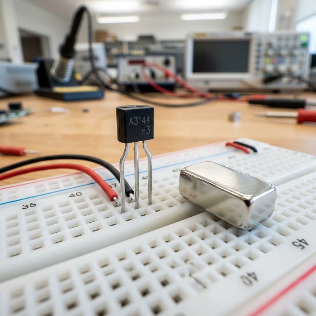
A digital trigger. Turns **ON** (outputs LOW) only when a South pole magnet is present. Turns **OFF** immediately when the magnet is removed. Used as limit switches. Example: A3144.
🔒 Bipolar Latching
Requires a South magnetic pole to turn **ON**, and remains latched ON even when the magnet is removed. It will only turn **OFF** (unlatch) when a North pole is introduced. Critical for BLDC motor speed encoders. Example: US1881.
Robotic & Automotive Applications
Because they are fully solid-state, Hall effect sensors suffer zero mechanical wear, are immune to dust, moisture, and vibration, and can operate at ultra-high frequencies. Common applications include:
- BLDC Motor Encoders: Three latching Hall sensors are embedded inside Brushless DC motors (BLDC) to track rotor magnet positions, providing the controller the exact timing needed for phase commutation.
- Speedometers & Tachometers: By mounting small magnets onto a spinning wheel or shaft and placing a Hall sensor nearby, every pass triggers a pulse. The frequency of these pulses corresponds to RPM.
- Non-Contact Limit Switches: Used in 3D printers and CNC machines to detect end-stops without physical wear or mechanical button fatigue.
Connecting a Hall Sensor to Arduino
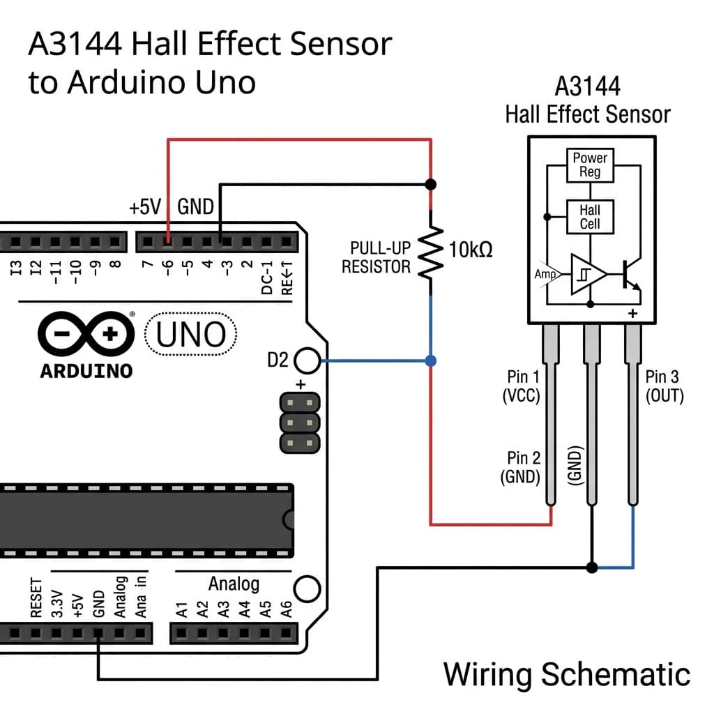
Standard digital Hall sensors like the A3144 are package in a 3-pin TO-92 structure: 1. **Pin 1:** VCC (+5V / +3.3V) 2. **Pin 2:** Ground (GND) 3. **Pin 3:** Digital Output (OUT) — Open-Collector structure requiring a **10kΩ pull-up resistor** connected to VCC.
**Basic Arduino Code for Magnetic Limit Switch:**
// Pin Definitions
const int HALL_PIN = 2; // Connect to Hall Sensor Pin 3 (OUT)
const int LED_PIN = 13; // Built-in LED

void setup() {
  pinMode(HALL_PIN, INPUT); // Pin relies on external 10k pull-up
  pinMode(LED_PIN, OUTPUT);
  Serial.begin(9600);
}

void loop() {
  int sensorState = digitalRead(HALL_PIN);

  // Open-collector logic: pulls LOW (0) when magnet is detected
  if (sensorState == LOW) {
    digitalWrite(LED_PIN, HIGH); // Turn LED ON
    Serial.println("🧲 Magnet Detected! (South Pole)");
  } else {
    digitalWrite(LED_PIN, LOW);  // Turn LED OFF
  }
  delay(100);
}
Magnetic Hall Effect Sensors & Component Availability in India
Sourcing common Hall Effect sensor ICs (such as the unipolar A3144, latching US1881, linear SS49E, or ready-to-use Hall speed-sensor modules) is incredibly simple across all major technology corridors and electronics hubs in India:
Mumbai
Find unipolar Hall switches (A3144) and current sensor ICs (ACS712) instantly at major retail/wholesale component vendors along Lamington Road.
Delhi
Purchase latching speed encoders and multi-pin magnetic breakout boards at wholesale rates in Lajpat Rai Market and Kucha Choudhary.
Bangalore
SP Road hosts the largest collection of industrial-grade linear and latching Hall sensors, plus developer breadboards and passive assortments.
Hyderabad
Gujarati Gali in Koti provides easy retail access to Hall speed tracking sensor modules and linear analog magnetic sensors.
Pune
Perfect for local engineering students; buy solid-state magnetic modules from tech-shops in Budhwar Peth or next-day online deliveries.
Chennai
Ritchie Street in Mount Road carries complete magnetic encoder sensor kits, neodymium ring magnets, and 10kΩ pull-up resistor packs.
Kolkata
Visit Chandni Chowk Market for affordable unipolar Hall Effect switches, digital proximity sensor boards, and hobby gear chassis.
Frequently Asked Questions
What is the Hall Effect and what is the Hall voltage?
The Hall Effect is the creation of a transverse voltage (the Hall Voltage) across an electrical conductor when a magnetic field is applied perpendicular to the direction of current flow. Discovered by Edwin Hall in 1879, it occurs because the Lorentz force deflects moving charge carriers (electrons) to one side of the conductor, building up a potential difference that can be measured and amplified.
What is the difference between a unipolar Hall switch and a latching Hall sensor?
A Unipolar Hall switch turns ON when a strong South magnetic pole is brought close, and turns OFF as soon as the magnet is removed. A Bipolar Latching Hall sensor requires a South pole to turn ON, and it remains ON even when the magnet is removed. It will only turn OFF when an opposite North magnetic pole is brought close, making latching sensors perfect for measuring rotational speed in BLDC motors.
Why do digital Hall sensors require a pull-up resistor?
Most digital Hall sensors (like the A3144 or US1881) have an open-collector output transistor. When no magnetic field is detected, the output floats disconnected. When a magnetic field triggers the sensor, it pulls the output pin directly to Ground (LOW). A pull-up resistor (typically 10kΩ) connected to VCC is required to hold the signal HIGH when the sensor is inactive.
Can a Hall effect sensor measure electrical current?
Yes. Since electrical current flowing through a conductor generates a proportional magnetic field (Ampere's Law), a Hall sensor placed near the wire can measure the magnetic field strength to determine the exact current without making physical electrical contact. ICs like the ACS712 current sensor utilize this exact principle.
How do you connect a TO-92 Hall Effect sensor to Arduino?
Connect Pin 1 (VCC) to the Arduino 5V pin. Connect Pin 2 (GND) to GND. Connect Pin 3 (OUT) to a digital input pin (like D2). Place a 10kΩ pull-up resistor between Pin 3 and Pin 1. In code, read the state using digitalRead() — a LOW reading indicates a magnetic field is present.
Conclusion
Hall Effect sensors bridge the physical gap between magnetism and solid-state electronics. Understanding charge deflection physics, unipolar/latching IC logic types, and correct resistor termination will help you implement high-precision contactless sensing in robotics, current monitoring, and speed encoder systems.
Ready to track magnetic fields? Interface your sensors with the Ultrasonic distance system, read 3-axis variables in the MPU6050 gyroscope primer, or examine digital signal pulling in I2C communication lines.
📚 References & Sources
Related Resources
MPU6050 Guide
Interface a full 6-axis gyroscope and accelerometer sensor.
Arduino Uno Guide
Master general microcontroller setup, inputs, and serial logging.
How Transistors Work
Learn open-collector semiconductor logic and resistor pull-ups.
How I2C Works
Contrast point-to-point digital sensors with synchronous two-wire buses.