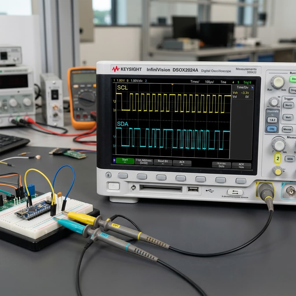
Introduction to the I2C Protocol
Invented by Philips Semiconductors (now NXP) in 1982, the I2C (Inter-Integrated Circuit)protocol—pronounced "eye-squared-see"—is a synchronous, half-duplex serial bus protocol. It was designed to allow simple, low-speed communications between multiple integrated circuits sitting on the same printed circuit board (PCB).
Before I2C, connecting multiple sensors or peripherals required dozens of dedicated input/output traces, cluttering boards and inflating pin counts. I2C solved this by introducing a shared bus architecture requiring only **two physical wires**: **SDA (Serial Data)** and **SCL (Serial Clock)**.
- I2C protocol utilizes two shared physical wires.
- Pull-up resistors establish high default voltage levels.
- Open-drain structures prevent electrical bus short circuits.
The Two-Wire Bus Topology & Pull-Up Resistors
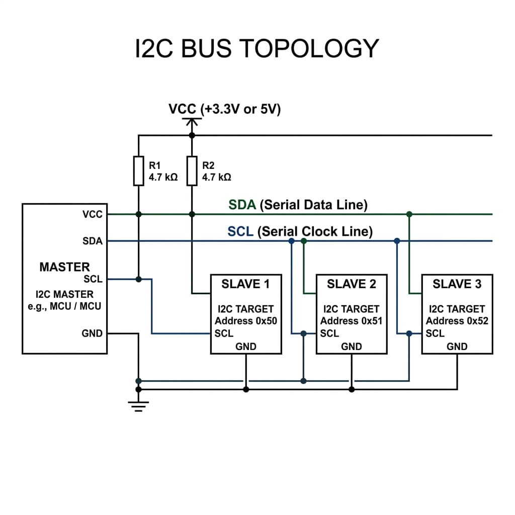
I2C uses a **shared bus topology**, meaning all controller (master) and target (slave) devices connect in parallel to the exact same SDA and SCL lines.
Why Pull-Up Resistors Are Mandatory
I2C pins have an open-drain (or open-collector) electrical structure. This means the internal transistors can pull SCL or SDA LOW to Ground, but they **cannot actively push the lines HIGH** to VCC.
To hold the lines in their default HIGH state when idle, two **pull-up resistors** (typically 4.7kΩ) must connect the SDA and SCL lines directly to the system supply voltage (VCC). If two devices communicate at the same time, this open-drain design prevents a devastating short circuit: if one device tries to output HIGH and another outputs LOW, the resistor limits current safely instead of blowing up transistors.
Understanding the I2C Message Frame Structure
Since multiple devices share the same data wires, communication is strictly structured. A complete I2C message packet consists of the following consecutive bit frames:
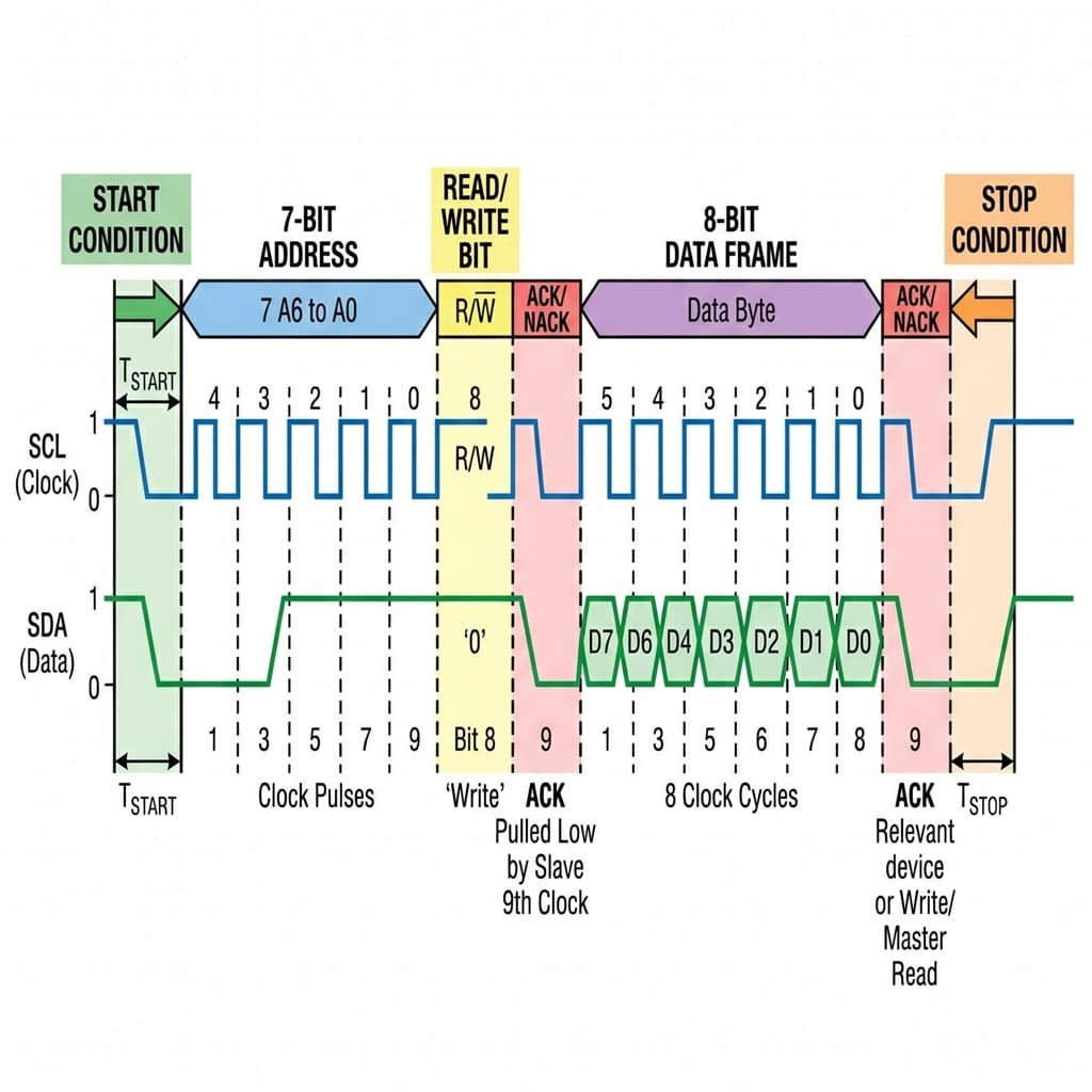
- Start Condition: The master pulls SDA LOW while SCL is still HIGH. This alerts the entire bus that a transmission is starting.
- Address Frame (7-bit): The master sends the unique 7-bit binary address of the target device it wishes to target. Every peripheral listens, but only the one with matching hardware address will respond.
- Read/Write Bit (1-bit): A single bit indicating direction. HIGH (1) tells the peripheral to send data to the master (Read); LOW (0) means the master will send data (Write).
- ACK/NACK Bit (1-bit): The targeted device pulls the SDA line LOW to acknowledge it received the address frame (ACK). If SCL stays HIGH, it signifies a failure (NACK).
- Data Frame (8-bit): 8 bits of actual payload data (like sensor registers or pixel maps).
- Stop Condition: The master releases SDA to go HIGH while SCL is HIGH, freeing the bus for other communications.
How I2C Compares to SPI and UART
Microcontrollers support three main serial protocols. Choosing the correct one is a trade-off between wire count, device counts, and speeds:
| Feature | I2C | SPI | UART |
|---|---|---|---|
| Wire Count | **2 Wires** (SDA, SCL) | 4+ Wires (MOSI, MISO, SCK, CS) | 2 Wires (TX, RX) |
| Topology | Multi-Master / Multi-Slave | Single Master / Multi-Slave | Point-to-Point (2 devices strictly) |
| Maximum Speed | Slower (100 kbps – 3.4 Mbps) | Extremely Fast (10 – 100+ Mbps) | Medium (Typically 115200 bps) |
| Best For | Multiple onboard low-speed sensors | Displays, SD Cards, high-speed RAM | Computer-MCU debugging, GPS links |
Using I2C with Arduino (Wire.h Library)
Arduino simplifies I2C using the built-in `Wire.h` library. On the Arduino Uno, the default I2C pins are: * **SDA:** Pin A4 (and the dedicated SDA pin near AREF) * **SCL:** Pin A5 (and the dedicated SCL pin near AREF)
**Example Code: Reading an I2C Sensor (e.g. MPU6050 Accelerometer):**
#include <Wire.h>

const int MPU_ADDR = 0x68; // Default 7-bit I2C Address of MPU6050

void setup() {
  Wire.begin();        // Join I2C Bus as Master
  Serial.begin(9600);

  // Awake the MPU6050 (write to Power Management Register 0x6B)
  Wire.beginTransmission(MPU_ADDR);
  Wire.write(0x6B); // Register Address
  Wire.write(0);    // Wakeup value (0)
  Wire.endTransmission();
}

void loop() {
  // Request 6 registers starting at 0x3B (Accelerometer data)
  Wire.beginTransmission(MPU_ADDR);
  Wire.write(0x3B);
  Wire.endTransmission(false); // Restart condition (hold bus active)

  Wire.requestFrom(MPU_ADDR, 6); // Request 6 bytes

  if (Wire.available() == 6) {
    int16_t ax = (Wire.read() << 8) | Wire.read();
    int16_t ay = (Wire.read() << 8) | Wire.read();
    int16_t az = (Wire.read() << 8) | Wire.read();

    Serial.print("AccX: "); Serial.print(ax);
    Serial.print(" | AccY: "); Serial.print(ay);
    Serial.print(" | AccZ: "); Serial.println(az);
  }
  delay(500);
}
I2C Sensor Modules & Pull-Up Resistor Component Availability in India
Sourcing common I2C sensors (such as the MPU6050 accelerometer, BMP280 barometer, or 1602 LCD with I2C backpacks) and critical bus passive components (like 4.7kΩ pull-up resistors) is extremely easy across major hardware and retail tech hubs in India:
Mumbai
Purchase high-accuracy MPU6050, OLED screens, and passive pull-up resistors directly from electronics dealers in Lamington Road, South Mumbai.
Delhi
Source robust synchronous I2C boards and development shields at competitive wholesale prices in Lajpat Rai Market and Chandni Chowk.
Bangalore
Find cutting-edge I2C targets, levels shifters, and logic analyzer tools directly at SP Road. Ideal for quick prototyping and startup supplies.
Hyderabad
Gujarat Gali in Koti stands out as Hyderabad's prime location for buying I2C backpacks, RTC modules (DS3231), and sensor modules.
Pune
Easily purchase high-frequency I2C breakout boards from developer-friendly stores in Budhwar Peth and fast regional online platforms.
Chennai
Visit Ritchie Street in Mount Road for reliable I2C hardware and standard 2-wire serial shields at affordable prices.
Kolkata
Explore the extensive shops at Chandni Chowk Market for cost-effective I2C LCD modules, gyro sensors, and board passives.
Frequently Asked Questions
What is I2C and how does it work?
I2C (Inter-Integrated Circuit) is a synchronous, multi-device, half-duplex serial communication protocol that allows multiple target integrated circuits (sensors, displays, EEPROMs) to communicate with a controller (microcontroller) using only two wires: SDA (Serial Data) and SCL (Serial Clock). Every device on the shared bus has a unique 7-bit address, allowing the master to selectively query specific devices.
Why does the I2C bus require pull-up resistors?
The I2C bus utilizes an open-drain (or open-collector) electrical structure. This means devices can only pull the SCL and SDA lines LOW (to GND); they cannot actively drive the lines HIGH. Pull-up resistors connected to VCC are required to passively pull the lines HIGH when no device is pulling them down, preventing short circuits when multiple devices communicate on the same wire.
What resistor values should be used for I2C pull-ups?
The standard pull-up resistor value is typically 4.7kΩ for 5V and 3.3V systems operating at standard speeds (100 kbps). For faster speeds (400 kbps) or high bus capacitance (long wires/many devices), lower values like 2.2kΩ or 1kΩ are used to pull the lines HIGH faster. For ultra-low power designs with short buses, higher values like 10kΩ can be used.
How do I2C, SPI, and UART compare?
I2C uses only 2 wires, supports multiple devices, but is slower (typically 100-400 kbps). SPI uses 4 wires, is full-duplex, and is extremely fast (10-50+ Mbps), but requires dedicated chip select pins for every target device. UART is asynchronous, requires only 2 wires, but is strictly point-to-point (only 2 devices) with no shared clock line.
What is clock stretching in the I2C protocol?
Clock stretching is a mechanism where a target device holds the SCL line LOW to pause the bus. If the controller tries to transmit data faster than a slow target sensor can process it, the target pulls SCL LOW. The controller detects this and waits until the target releases SCL HIGH before sending the next clock pulse and data bits.
Conclusion
The I2C protocol is the absolute standard for low-speed component communications on boards and prototyping systems. Learning to calculate pull-up resistor needs, understanding packet frame timings, and knowing how to debug address conflicts will make your embedded hardware designs reliable, modular, and highly integrated.
Ready to bus data? Hook up your I2C devices to the Ultrasonic Sensor guide, read registers from the MPU6050 Inertial Unit, or examine I2C pull-up parameters in Smartphone Motherboard routing.
📚 References & Sources
Related Resources
MPU6050 Guide
Interface the standard MPU6050 6-DOF IMU sensor using I2C commands.
Arduino Uno Guide
Master general microprocessor pins, A4/A5 layout, and basic registers.
How USB-C Works
Contrast synchronous board buses with high-speed USB standards.
How Transistors Work
Learn open-drain transistor physics and why pull-up resistors are required.