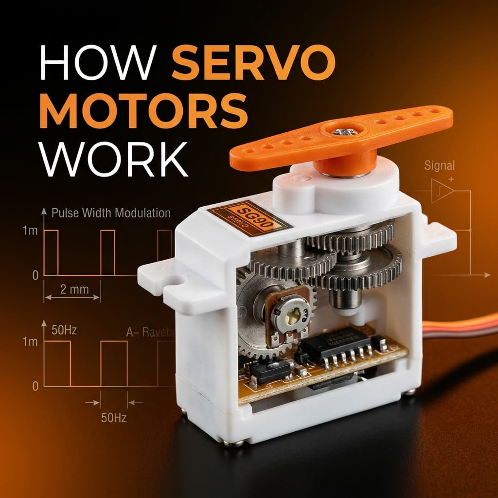
Inside a Servo Motor: 4 Core Components
- [Servo motor] [converts] [PWM pulse width to shaft angle]
- [Internal potentiometer] [provides] [closed-loop position feedback]
- [Gear train] [multiplies] [torque while reducing speed]
⚙️ DC Motor
Small coreless or brushed DC motor — runs at high RPM with low torque. The raw power source.
🔩 Gear Train
3–5 reduction stages (plastic in SG90, metal in MG996R). Reduces speed to ~60 RPM while multiplying torque 100–300x.
🎛️ Potentiometer
Linked to output shaft. Its wiper voltage tells the control board the exact current angle of the output shaft.
🖥️ Control Board
PWM decoder + error amplifier + H-bridge driver. Continuously compares target angle (from PWM) to actual angle (from pot) and drives motor to eliminate the error.
The Servo PWM Control Signal: Pulse Width to Angle
Standard hobby servos use a 50 Hz PWM signal (20 ms period). The pulse width (not duty cycle) encodes the target position:
| Pulse Width | Position | Arduino servo.write() |
|---|---|---|
| 1.0 ms (1000 µs) | 0° (full counter-clockwise) | servo.write(0) |
| 1.5 ms (1500 µs) | 90° (center/neutral) | servo.write(90) |
| 2.0 ms (2000 µs) | 180° (full clockwise) | servo.write(180) |
servo.writeMicroseconds() instead of servo.write() for smooth animation — it gives 1 µs resolution instead of 1° resolution. Range: 1000–2000 µs for most servos (some extend to 500–2500 µs).SG90 vs MG996R vs Continuous Rotation: Which Servo to Choose?
| Model | Torque | Gears | Weight | Best For |
|---|---|---|---|---|
| SG90 Micro | 1.8 kg·cm | Plastic | 9 g | Small arms, RC planes, light mechanisms |
| MG996R | 9.4–11 kg·cm | Metal | 55 g | Robot arms, camera gimbals, RC cars |
| DS3218 | 20 kg·cm | Metal | 60 g | Heavy robot joints, industrial demos |
| Continuous | N/A (speed) | Varies | Varies | Wheeled robots, conveyors, winches |
Wiring a Servo to Arduino: Step-by-Step
- Connect GND (brown wire): Servo GND to Arduino GND (and to negative of any external 5V supply).
- Connect VCC (red wire): For SG90: Arduino 5V pin is acceptable for 1 servo. For MG996R or multiple servos: use a separate 5V/2A supply — do NOT power from Arduino 5V pin (it overloads the onboard regulator).
- Connect Signal (orange/yellow wire): To any Arduino digital pin (PWM not strictly required — the Servo library bitbangs the 50 Hz signal on any pin).
- Add 100 µF capacitor: Between servo VCC and GND near the servo connector. Absorbs current spikes from motor stalls and prevents Arduino resets.
Frequently Asked Questions
How does a servo motor know its position?
Inside every servo is a potentiometer linked to the output shaft. As the shaft rotates, the pot wiper voltage changes proportionally. The control board compares this feedback voltage to the target (derived from PWM pulse width) and drives the DC motor to close the error — this is the closed-loop control system.
What is the PWM signal format for servo motors?
Standard hobby servos use 50 Hz (20 ms period) PWM. Pulse width encodes position: 1 ms = 0°, 1.5 ms = 90° (neutral), 2 ms = 180°. Arduino Servo library auto-generates this. Use servo.writeMicroseconds(1500) for 90° with microsecond precision.
What is the difference between SG90 and MG996R servo?
SG90: 9g micro servo with plastic gears, 1.8 kg·cm torque — for lightweight applications. MG996R: 55g with metal gears, 9.4 kg·cm torque — for robot arms, pan-tilt mounts, heavier loads. Use MG996R when plastic gears would strip under load.
How do I control a servo with Arduino?
#include <Servo.h>, then Servo myServo; myServo.attach(9); myServo.write(90); Use an external 5V supply for metal-gear servos — do not power from Arduino 5V pin for MG996R or multiple servos.
What is a continuous rotation servo?
A continuous rotation servo has the feedback pot replaced with a fixed divider — it loses position control but gains bidirectional spin. Pulse width controls speed/direction: 1 ms = full reverse, 1.5 ms = stop, 2 ms = full forward. Used in wheeled robots and conveyor mechanisms.
Conclusion
Servo motors pack a DC motor, gear train, potentiometer, and PID control loop into a remarkably compact package — making precise angular control accessible with just a single PWM wire. Master the pulse-width-to-angle mapping, choose the right torque class for your load, and always power metal-gear servos from a dedicated supply. Your robotics and RC projects will be far more reliable as a result.
Need full bidirectional speed control? See how H-bridges work for DC motors. For step-based positioning, read about stepper motors.
📚 References & Sources
Related Resources
How Stepper Motors Work
Open-loop step-based positioning: NEMA 17 and A4988 driver
How H-Bridges Work
Bidirectional DC motor control using L298N and MOSFETs
What Is PWM?
Master pulse-width modulation for servo angle and motor speed
How PID Controllers Work
The same closed-loop logic inside every servo motor