GPIO Fundamentals: 3.3V Logic, Current Limits & Critical Rules
- [Raspberry Pi GPIO] [operates at] [3.3V — not 5V tolerant like Arduino]
- [Each GPIO pin] [sources or sinks] [maximum 16 mA safely]
- [5V input on GPIO pin] [permanently destroys] [the BCM2711 SoC]
Special-Function GPIO Pins: I2C, SPI, UART & Hardware PWM
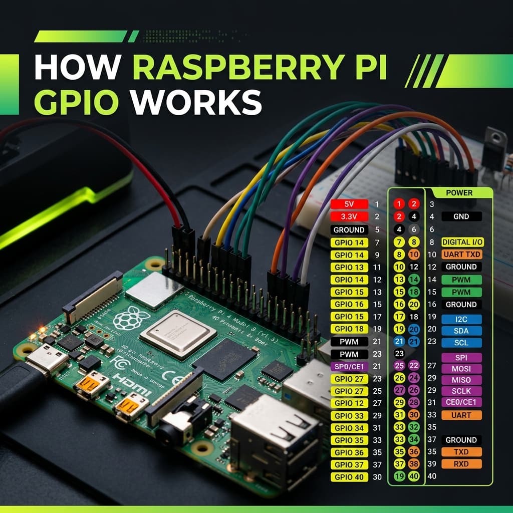
Most GPIO pins are general-purpose digital I/O, but these have dedicated hardware peripherals mapped to them:
| GPIO (BCM) | Alt Function | Physical Pin | Notes |
|---|---|---|---|
| GPIO2 (SDA) | I2C SDA | Pin 3 | I2C data line — has built-in 1.8kΩ pull-up |
| GPIO3 (SCL) | I2C SCL | Pin 5 | I2C clock line — has built-in 1.8kΩ pull-up |
| GPIO14 (TXD) | UART TX | Pin 8 | Serial transmit — disable console for use |
| GPIO15 (RXD) | UART RX | Pin 10 | Serial receive — disable console for use |
| GPIO12 | Hardware PWM0 | Pin 32 | True hardware PWM — precise frequency |
| GPIO13 | Hardware PWM1 | Pin 33 | True hardware PWM channel 2 |
| GPIO10 (MOSI) | SPI0 MOSI | Pin 19 | SPI Master Out Slave In |
| GPIO9 (MISO) | SPI0 MISO | Pin 21 | SPI Master In Slave Out |
| GPIO11 (SCLK) | SPI0 Clock | Pin 23 | SPI clock line |
Python GPIO Control: RPi.GPIO vs gpiozero
RPi.GPIO (Low-Level)
gpiozero (Recommended)
Frequently Asked Questions
What voltage do Raspberry Pi GPIO pins use?
3.3V logic — NOT 5V tolerant. HIGH = 3.3V, LOW = 0V. Connecting 5V to GPIO input permanently destroys the pin. Use a voltage divider (1kΩ + 2kΩ) or level shifter for all 5V device interfaces.
What is the difference between BCM and BOARD GPIO numbering?
BCM uses Broadcom SoC GPIO numbers (GPIO17, GPIO27 etc.) — used in most tutorials and libraries. BOARD uses physical pin numbers 1–40. In RPi.GPIO: GPIO.setmode(GPIO.BCM) or GPIO.setmode(GPIO.BOARD). BCM is recommended for portability.
How many GPIO pins does a Raspberry Pi have?
The 40-pin header (Pi 2/3/4/5) has 26 usable GPIO pins. Remaining pins: 5V×2, 3.3V×2, GND×8, ID_SD/ID_SC (HAT EEPROM). Pi 1 had only 17 GPIO on a 26-pin header.
How do I control GPIO in Python on Raspberry Pi?
gpiozero (recommended): from gpiozero import LED, Button. RPi.GPIO (low-level): import RPi.GPIO as GPIO; GPIO.setmode(GPIO.BCM); GPIO.setup(17, GPIO.OUT); GPIO.output(17, True); GPIO.cleanup(). Always call cleanup() with RPi.GPIO to reset pins.
Can Raspberry Pi GPIO pins be damaged by over-current or over-voltage?
Yes. Max 16mA per pin, 50mA total. Always use a resistor with LEDs (220–470Ω). Input voltage above 3.3V destroys GPIO. For motors/relays, use a MOSFET or transistor buffer — never connect directly to GPIO.
Conclusion
The Raspberry Pi GPIO transforms a $35 computer into a physical computing platform capable of interfacing with virtually any electronic component — from a simple LED to a full robotics system. The critical rules: respect the 3.3V logic level, stay within 16mA per pin, and always use gpiozero's high-level abstractions for clean, safe Python code.