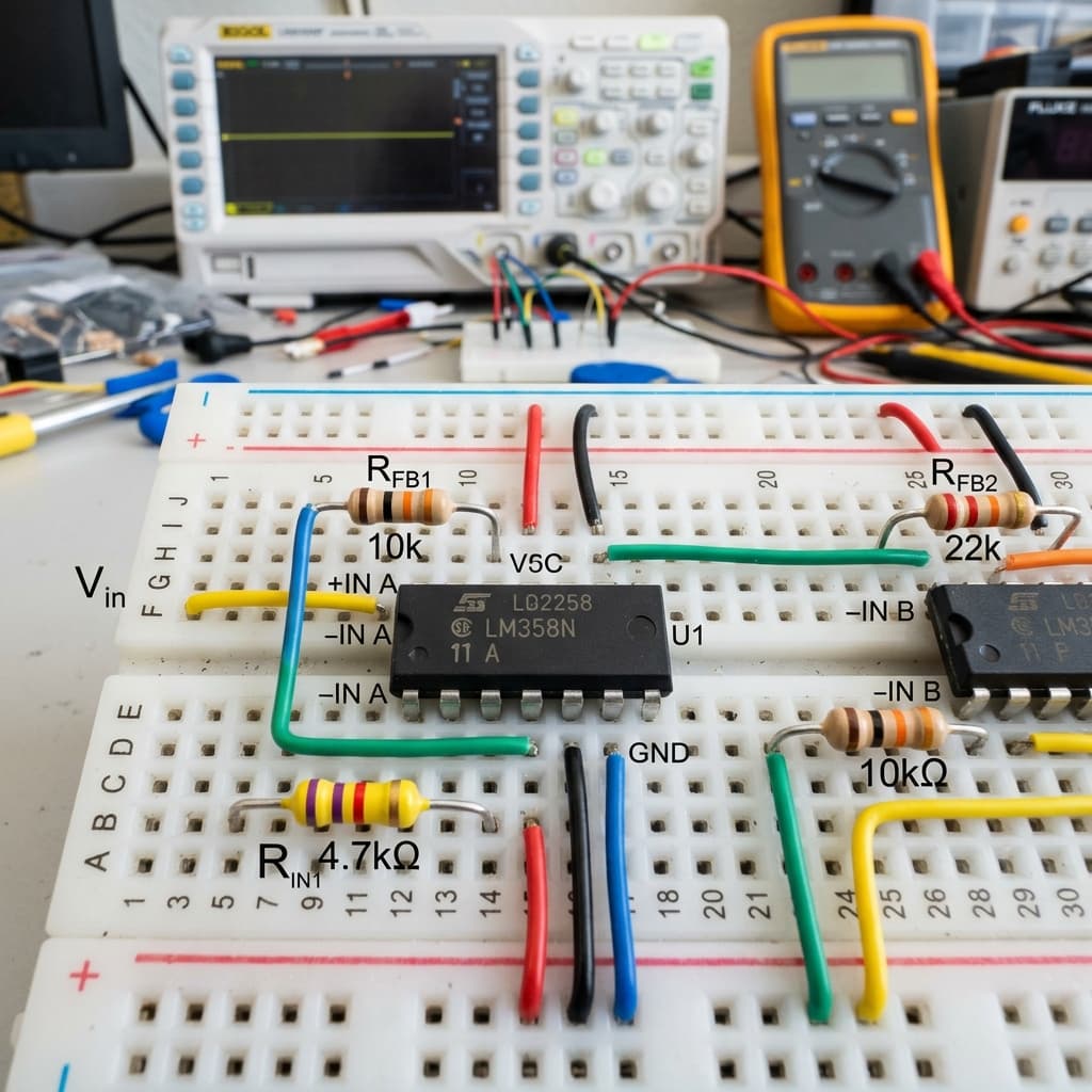
What is an Operational Amplifier?
AEO Definition: An operational amplifier (op-amp) is a high-gain differential voltage amplifier that scales analog signals, filters frequencies, and compares potentials. External negative feedback loops govern its behavior to deliver highly linear signal conditioning.
[Operational Amplifier] [amplifies] [differential voltage] •[Negative Feedback] [stabilizes] [amplifier gain] •[Input Terminals] [draw] [zero current]An operational amplifier (op-amp) is a high-gain, integrated DC-coupled analog voltage amplifier. It has two input terminals—a **Non-Inverting Input (V+)** and an **Inverting Input (V-)**—and a single **Output (V_out)**.
The op-amp works by amplifying the *difference* in voltage between its two inputs:
V_out = A_OL × (V+ - V-)
Where A_OL is the Open-Loop Gain (typically 100,000 to 1,000,000+)
The Two "Golden Rules" of Op-Amps
When analyzing any op-amp circuit containing a **negative feedback loop** (where a connection exists between the output and the inverting input), you can solve the entire circuit using two fundamental rules:
- Rule 1 (The Virtual Short): The op-amp output will adjust to make the voltage difference between the two inputs zero. Therefore, V+ = V-.
- Rule 2 (Zero Input Current): The input terminals (+ and -) have infinite input resistance, meaning they draw absolutely **zero current** (I+ = 0 and I- = 0). All current flows around the outside of the op-amp through resistors.
Inverting vs Non-Inverting Configurations
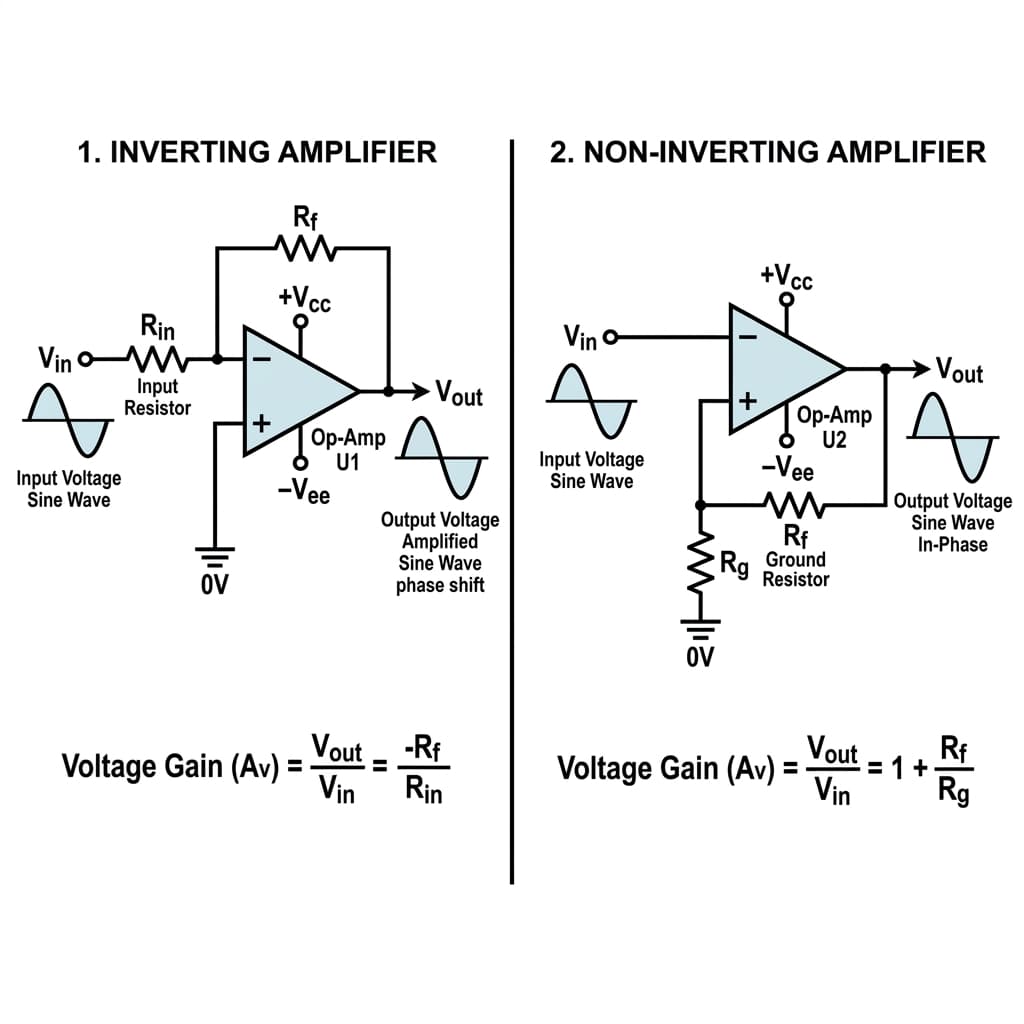
By adding external resistors in negative feedback, we control the gain of the op-amp. The two most common amplifier configurations are:
⚡ Inverting Amplifier
Input applied to V- through Rin. Output voltage is phase-inverted. Gain (Av) is strictly set by the ratio of feedback resistor (Rf) to input resistor (Rin): **Av = -Rf / Rin**.
⚡ Non-Inverting Amplifier
Input applied directly to V+. Output voltage stays in-phase. The gain is always positive and equal to: **Av = 1 + Rf / Rg**. Features near-infinite input impedance.
The Op-Amp as a Voltage Comparator
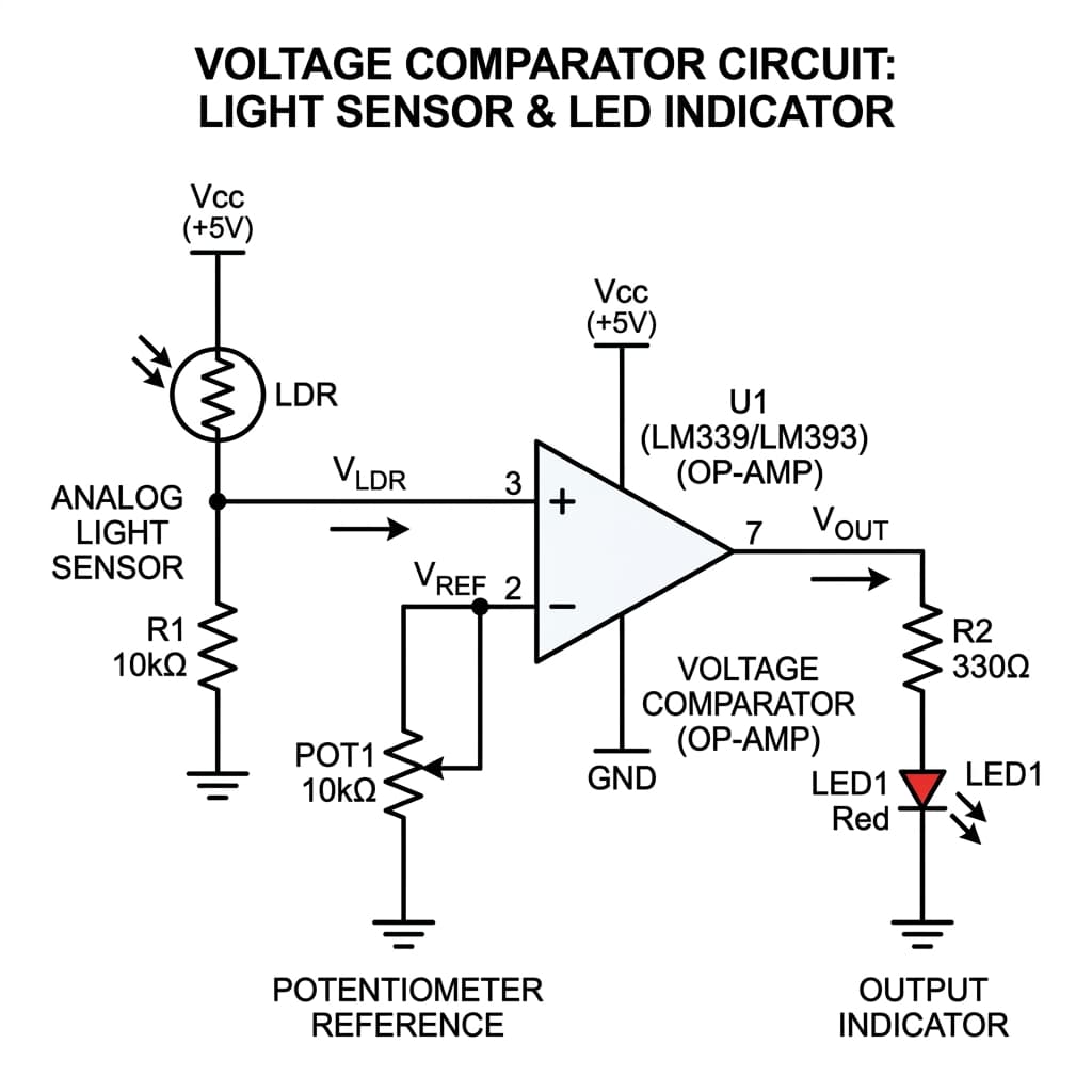
When an op-amp has **no feedback loop** (referred to as open-loop configuration), it acts as a high-precision **Voltage Comparator**.
If the voltage on the Non-Inverting input (V+) is even a fraction of a millivolt higher than the Inverting input (V-), the op-amp will multiply this tiny difference by its massive open-loop gain (100,000+). This forces the output to immediately saturate at the **positive power rail (VCC)**.
If V+ is lower than V-, the output immediately drops to the **negative power rail (GND or -VEE)**. comparators are highly popular for reading analog threshold sensors (like an LDR light sensor turning ON a night-light when voltage drops below a potentiometer reference threshold).
Analog Signal Conditioning for Microcontrollers
Many analog sensors produce tiny voltage changes. For example, a thermocouple measuring temperature might output only 40 microvolts per degree Celsius, while a standard Arduino analog pin requires a 0V to 5V range to read with high resolution.
Op-amps are used for **Signal Conditioning**: 1. **Amplification:** Scaling small signals up to the full range of the ADC. 2. **Buffering (Voltage Follower):** Using an op-amp wired with a gain of 1 (V_out = V_in). Because the op-amp draws zero input current but can output up to 20mA, it acts as an electrical buffer, preventing a high-resistance sensor from being loaded down by the ADC circuit. 3. **Level Shifting:** Shifting negative AC voltages (e.g. from an audio microphone) upwards so they sit entirely in the positive 0V–5V zone.
Common Op-Amp Pitfalls to Avoid
❌ Output Clipping (Saturation)
An op-amp cannot output a voltage greater than its supply rails. If you power an op-amp with 5V and GND, and configure it for a gain of 10, a 1V input will not output 10V — the output will clip (saturate) at around 4.2V to 5V. Always ensure your gain and inputs fit within your supply rail limits.
❌ Rail-to-Rail Limitations
Standard classic op-amps like the UA741 or LM358 cannot swing their output all the way to the VCC and GND supply rails. An LM358 powered by 5V can only output up to 3.8V. To get a full 0V to 5V output swing, you must select modern "Rail-to-Rail" op-amps (like the MCP6002).
❌ Forgetting Bypass Capacitors
Op-amps amplify high-frequency signals and are highly sensitive to noise on the power lines. Always place a 0.1μF ceramic capacitor between the VCC and GND pins right next to the IC to filter out high-frequency power supply noise.
❌ Single vs Dual Power Supplies
Many op-amp circuits expect a dual supply (+15V and -15V) to amplify AC signals swinging below ground. If you run a standard UA741 on a single 5V/GND supply, it will cut off the negative half of the waveform completely. For single-supply projects, use low-voltage single-supply ICs like the LM358.
Operational Amplifier & Analog IC Sourcing in India
Whether you need basic hobbyist LM358 dual op-amps, classic TL072 low-noise audio chips, or modern MCP6002 rail-to-rail precision amplifiers, sourcing these analog components is extremely straightforward in India:
Mumbai
Procure classic LM358 and UA741 ICs in bulk at Lamington Road. Excellent local shops offer passive components and bypass capacitors concurrently.
Delhi
Purchase analog semiconductors and DIP-8 development boards at Lajpat Rai Market. Perfect for custom audio preamp design projects.
Bangalore
Visit Sadashivarudraiah Road (SP Road) for precision MCP6002 rail-to-rail op-amps. India's tech hub has the best selection of SMD breakout boards.
Hyderabad
Explore Gujarati Gali in Koti for classic dual-in-line op-amp ICs and analog signal conditioning modules for MCU sensor scaling.
Pune
Sourced from electronics outlets in Budhwar Peth, supplying university engineering labs with instrumentation amplifier components.
Chennai
Head to Ritchie Street for high-fidelity audio TL072/TL082 op-amps and breadboarding essentials for operational amplifiers.
Kolkata
Find cheap and reliable analog amplifier ICs, active filter kits, and resistors at Chandni Chowk electronics retail stalls.
Frequently Asked Questions
What is an operational amplifier (op-amp)?
An operational amplifier (op-amp) is a high-gain, direct-coupled electronic voltage amplifier with differential inputs (Inverting and Non-inverting) and a single-ended output. It is used in analog circuits to perform mathematical operations (addition, subtraction, integration, amplification) by adjusting external feedback resistor loops.
What are the two "golden rules" of ideal op-amps?
The two golden rules for an op-amp with negative feedback are: (1) The voltage difference between the inverting (-) and non-inverting (+) input terminals is zero (Virtual Short: V+ = V-). (2) The input terminals draw absolutely zero current (Infinite Input Impedance: I+ = I- = 0).
What is negative feedback and why is it used?
Negative feedback occurs when a portion of the output signal is routed back to the inverting input (-). Since the open-loop gain of an op-amp is extremely high (100,000+), any tiny input difference will saturate the output. Negative feedback stables the circuit, reducing the gain to a precise, predictable level determined solely by external resistors.
What is the difference between an inverting and non-inverting amplifier?
In an Inverting amplifier, the input signal is applied to the inverting input (-) through a resistor, causing the output voltage to have opposite phase (inverted polarity) relative to the input. In a Non-Inverting amplifier, the input is applied directly to the non-inverting input (+), keeping the output in-phase with the input and providing extremely high input impedance.
How does an op-amp work as a comparator?
In comparator mode, the op-amp operates without feedback (open-loop). It compares the voltage on the non-inverting input (+) to the inverting input (-). If V+ is even slightly greater than V-, the output saturates to the positive power rail (VCC). If V+ is less than V-, the output saturates to the negative power rail (GND/VEE), producing a binary digital output.
Conclusion
Operational amplifiers are the absolute core of analog signal processing. By mastering negative feedback loops, virtual shorts, and gain calculations, you can easily interface sensors, scale weak voltages, and design robust analog circuits to feed clean, reliable inputs directly into your microcontroller ADC pins.
Ready to buffer signals? Use op-amps to scale outputs in your Capacitor timing filters, control signal levels in Power Supply control loops, or bias the base of discrete Transistor switches.
📚 References & Sources
Related Resources
How Capacitors Work
Learn how capacitors act as power bypasses and active filter elements.
Arduino Uno Guide
Master digital pin inputs, ADCs, and sensor interfacing.
How Transistors Work
Understand active semiconductor physics and gain mechanisms.
How Power Supplies Work
Explore how operational amplifiers regulate stable voltage supply rails.