What Is CAN Bus?
Developed by Bosch in 1983 and standardized in 1993, CAN was created to solve a specific automotive engineering problem: as modern cars added more and more electronic control units (ECUs), connecting them all with individual wires became impractical. A 1980s luxury car might need over 2km of wiring — a CAN bus replaces this with a simple 2-wire network.
Today, CAN is used far beyond automotive: robotics (ROS2 CAN drivers), industrial automation (CANopen), medical devices, and aerospace all rely on CAN's exceptional noise immunity and fault-tolerant design.
Differential Signaling: Why CAN Is Noise-Immune
Unlike single-ended protocols (UART, I2C), CAN uses two complementary wires:
| Bit State | CAN-H Voltage | CAN-L Voltage | Differential (H−L) |
|---|---|---|---|
| Dominant (0) | 3.5V | 1.5V | 2.0V |
| Recessive (1) | 2.5V | 2.5V | 0.0V |
Electrical noise from the engine or other interference adds equal voltage to both wires simultaneously — so the difference (H−L) stays the same, making CAN effectively immune to common-mode electromagnetic interference (EMI). This is why CAN is trusted in harsh automotive and industrial environments.
CAN Data Frame Structure
A CAN data frame consists of multiple well-defined fields:
- SOF (Start of Frame, 1 bit): Dominant bit signaling frame start, synchronizes all nodes.
- Arbitration Field (11 or 29 bits): The Message ID. Lower ID = higher priority. All nodes transmit simultaneously; arbitration determines winner without data loss.
- RTR (Remote Transmission Request, 1 bit): Distinguishes data frames from remote frames requesting data.
- DLC (Data Length Code, 4 bits): Specifies payload length (0–8 bytes for classic CAN).
- Data Field (0–64 bytes): The actual payload — sensor readings, commands, status bytes.
- CRC (15 bits + 1 delimiter): Cyclic Redundancy Check for error detection.
- ACK Field (2 bits): Receiving nodes pull this dominant to acknowledge receipt.
- EOF (7 bits): End of frame marker — 7 recessive bits.
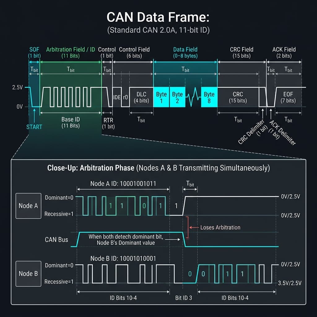
Fig 1: Standard CAN Data Frame — SOF, Arbitration (Message ID), Control, Data, CRC, and ACK fields
Arduino CAN Bus with MCP2515
The MCP2515 is an SPI-connected CAN controller IC paired with a TJA1050 CAN transceiver module. Widely available for under $2:
// Arduino CAN Bus Sender using MCP2515
// Library: mcp_can by coryjfowler
#include <mcp_can.h>
#include <SPI.h>

MCP_CAN CAN(10); // CS pin = D10

void setup() {
  Serial.begin(115200);
  if (CAN.begin(MCP_ANY, CAN_500KBPS, MCP_8MHZ) == CAN_OK) {
    Serial.println("CAN bus initialized at 500 kbps");
  }
  CAN.setMode(MCP_NORMAL);
}

void loop() {
  byte data[4] = {0x01, 0x02, 0x03, 0x04}; // 4-byte payload

  // Send with arbitration ID 0x123, standard frame (11-bit ID)
  byte result = CAN.sendMsgBuf(0x123, 0, 4, data);

  if (result == CAN_OK) {
    Serial.println("CAN frame sent successfully");
  } else {
    Serial.println("Error sending CAN frame");
  }
  delay(100); // 10 Hz transmission rate
}
Frequently Asked Questions
What is CAN bus and why is it used in cars?
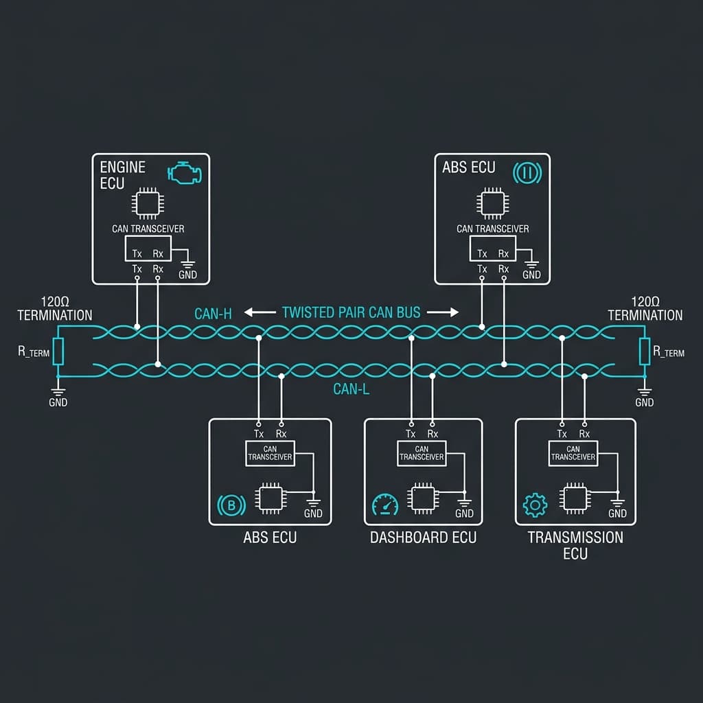
CAN bus replaces heavy wiring harnesses in vehicles — instead of direct point-to-point wiring between every ECU, all modules share a single twisted pair. A modern car has 70+ ECUs communicating on multiple CAN buses.
How does CAN bus arbitration work?
CAN uses CSMA/CA — multiple nodes can transmit simultaneously. Each monitors the bus while transmitting. When a node detects a dominant bit where it sent a recessive bit, it loses arbitration and backs off. The lowest Message ID always wins.
What is the difference between CAN and CAN FD?
Classic CAN: 1 Mbps max, 8 bytes max data. CAN FD: 8 Mbps data-phase speed, 64 bytes max data. CAN FD was developed for automotive ADAS sensor data and OTA firmware updates.
What is OBD-II and how does it use CAN?
OBD-II is the standardized vehicle diagnostic interface (under-dashboard port). It provides access to the vehicle's CAN bus. Scanners send standard PIDs over CAN to request engine RPM, coolant temperature, fault codes (DTCs), and more.
What termination resistors does CAN bus need?
CAN bus needs 120Ω resistors at each physical end of the bus. These match the cable's characteristic impedance and prevent signal reflections. Without them, high-speed communication errors and noise are common.
📚 References & Sources
Related Resources
UART vs SPI vs I2C
Compare CAN with other serial protocols for embedded systems.
How I2C Works
The 2-wire protocol used alongside CAN for on-board sensors.
Tesla Autopilot Sensors
How ADAS sensor data flows over automotive-grade buses.
How WiFi Works
Wireless alternative for IoT devices vs wired CAN networks.