How Magnetic Speed Tracking Works
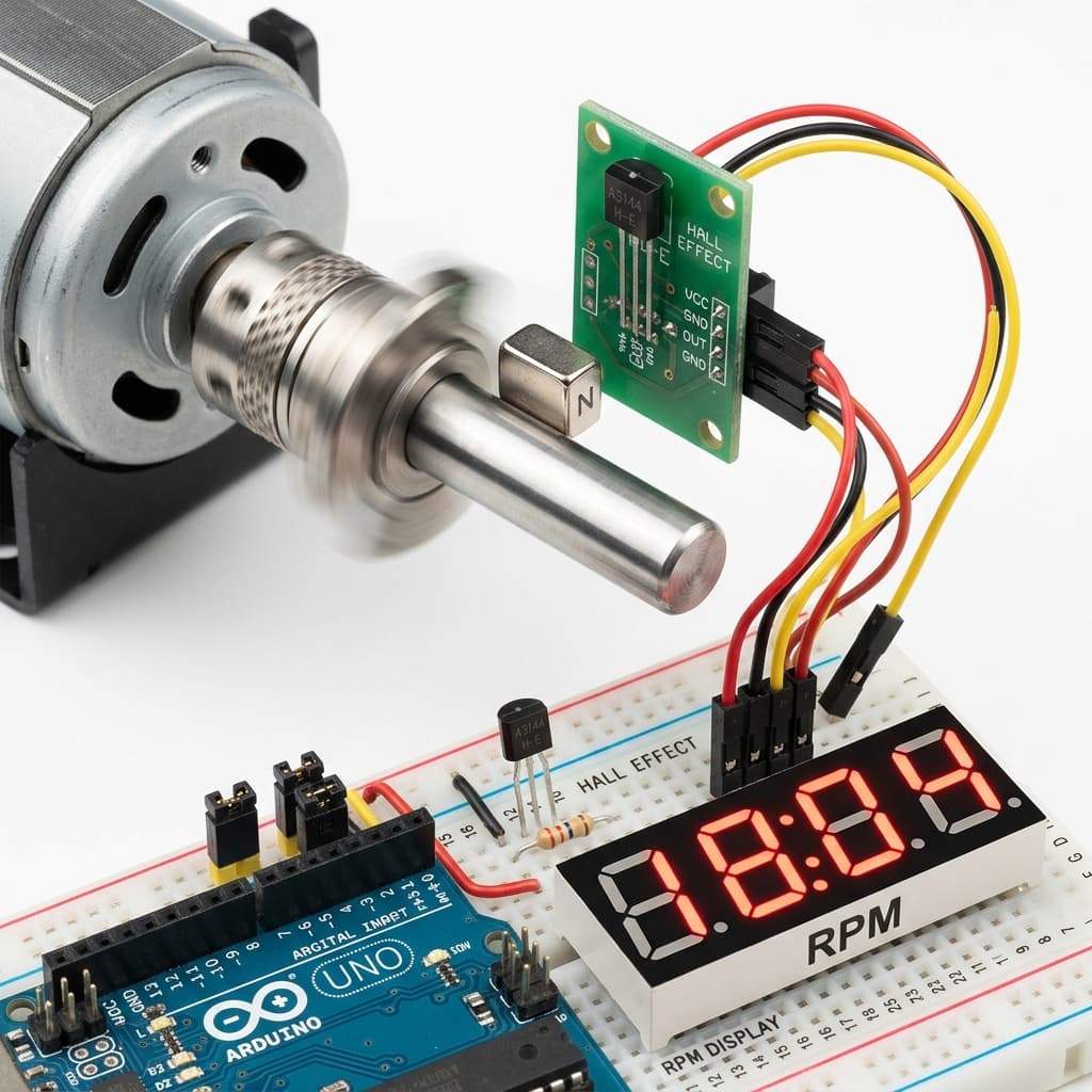
To track rotational speed (RPM) or linear speed (speedometer), we mount a small permanent magnet (typically a strong neodymium disc) onto the rotating component (wheel, shaft, or motor gear). A digital unipolar Hall sensor (like the A3144) is mounted nearby on a stationary bracket.
Each time the magnet completes one rotation and passes the sensor face, it triggers the sensor. This pulls the digital output pin LOW. When the magnet passes, the output floats back to HIGH via a pull-up resistor. Counting these high-to-low transitions provides the rotational rate.
- Tachometers count magnetic rotational transitions.
- Hardware interrupts capture high-speed pulse timing.
- Rotor speed calculations compute revolutions per minute.
Why Hardware Interrupts are Essential
Consider a shaft spinning at 3,000 RPM. This equates to 50 rotations per second. The magnet passes the sensor in just a few hundred microseconds. If the microcontroller is busy writing to an LCD or running a delay function in the main loop, it will miss the passing magnet.
Using Hardware Interrupts (e.g. attachInterrupt on Arduino pins D2 or D3) fixes this problem. An interrupt monitors the hardware pin directly. The instant the voltage drops from 5V to 0V (a Falling edge), the MCU suspends its main routine, executes a tiny Interrupt Service Routine (ISR) to increment a pulse counter, and returns to main code. This guarantees zero missed cycles.
Calculating RPM and Linear Velocity
To translate raw pulse counts into Revolutions Per Minute, we count pulses over a fixed sample period (e.g., 1000 ms) and calculate:
RPM = (Pulses / Magnets) * (60,000 / SamplePeriod)
To calculate linear vehicle speed in km/h, compute the circumference and factor in diameter (in mm):
Circumference (m) = (Diameter * π) / 1000
Speed (km/h) = (RPM * Circumference * 60) / 1000
Tachometer Wiring & Code
Connect the A3144 Hall sensor to the Arduino: 1. **VCC:** 5V 2. **GND:** GND 3. **OUT:** Pin 2 (Interrupt Pin 0) — add a 10kΩ pull-up resistor between OUT and VCC.
// Arduino Tachometer (RPM Counter) Code
const int INTERRUPT_PIN = 2; // Interrupt D2
volatile unsigned long pulseCount = 0;
volatile unsigned long lastPulseTime = 0;
volatile unsigned long minPeriod = 2; // Software debounce: 2ms (30,000 RPM max)

unsigned long lastUpdate = 0;
const unsigned long UPDATE_INTERVAL = 1000; // 1 second update

void IRAM_ATTR countPulse() {
  unsigned long currentTime = millis();
  // Simple software debounce to filter noise/multiple triggers
  if (currentTime - lastPulseTime > minPeriod) {
    pulseCount++;
    lastPulseTime = currentTime;
  }
}

void setup() {
  Serial.begin(115200);
  pinMode(INTERRUPT_PIN, INPUT_PULLUP);
  attachInterrupt(digitalPinToInterrupt(INTERRUPT_PIN), countPulse, FALLING);
  Serial.println("RPM Meter Initiated.");
}

void loop() {
  unsigned long now = millis();
  if (now - lastUpdate >= UPDATE_INTERVAL) {
    noInterrupts(); // Temporarily disable interrupts for atomic read
    unsigned long pulses = pulseCount;
    pulseCount = 0;
    interrupts(); // Re-enable interrupts

    // Calculate RPM (1 magnet per rotation)
    float rpm = (float(pulses) / 1.0) * (60000.0 / UPDATE_INTERVAL);

    Serial.print("RPM: ");
    Serial.println(rpm, 0);

    lastUpdate = now;
  }
}
Tachometers, Speed Sensors & Neodymium Magnets Sourcing in India
Sourcing A3144 Hall switches, speed sensor breakout boards, or tiny neodymium disc magnets in India is very convenient:
Mumbai
Purchase digital A3144 TO-92 sensors and neodymium magnets at electronics retail outlets on Lamington Road.
Delhi
Find pre-assembled LM393 comparator-based Hall speed sensor modules in Kucha Choudhary (Lajpat Rai Market).
Bangalore
SP Road vendors offer a wide variety of neodymium ring/disc magnets and active sensor modules.
Hyderabad
Gujarati Gali in Koti is the best local source for A3144 switches, pull-up resistors, and breadboards.
Pune
Local outlets in Budhwar Peth stock speed feedback sensor arrays and Arduino boards for engineering students.
Chennai
Find active speed tracking breakout modules and magnets on Ritchie Street (Mount Road).
Kolkata
Visit Chandni Chowk for affordable magnetic switches, wire rolls, and developer supplies.
Frequently Asked Questions
What sensor should I use for a Hall effect tachometer?
The A3144 unipolar digital Hall switch is the standard choice. It operates as an active-low switch, meaning it pulls the output signal directly to Ground when a South magnetic pole is close, and releases the signal when the magnet is removed. This rapid state change creates clear digital pulses ideal for microcontrollers.
Why should I use hardware interrupts instead of digitalRead for RPM tracking?
At high RPM, magnets pass the sensor in a fraction of a millisecond. If you use standard digitalRead() in loop(), delay() calls or other tasks might cause the MCU to miss pulses. Hardware interrupts instantly halt the main code loop to execute a pulse count routine (ISR) the microsecond the sensor pin changes state, ensuring zero missed pulses.
What is the formula to convert sensor pulses into RPM?
The RPM calculation formula is: RPM = (Pulses / Magnets) * (60,000 / SamplePeriod). Where: Pulses is the count detected during the timing window, Magnets is the number of magnets mounted on the rotating wheel (usually 1), and SamplePeriod is the timing window duration in milliseconds (typically 1000 ms).
How do you prevent false triggers and double pulses in a tachometer?
Double pulses occur due to electrical noise or when the magnet hovers at the switching threshold. You can prevent this in software by implementing a simple debounce check in the interrupt handler: ignore any interrupt that fires within a short dead-time window (e.g., 2 milliseconds) since the last registered pulse.
How do you calculate speed in km/h or mph from RPM?
To compute linear speed, find the wheel circumference: Circumference = Wheel Diameter * π. Speed is then calculated as: Distance per minute = RPM * Circumference. Convert this value to the desired units: Speed (km/h) = (Distance per minute * 60) / 1,000,000 (if diameter was in millimeters).
Conclusion
Building a DIY tachometer connects physical motion, electromagnetism, and micro-controller software. By choosing the unipolar A3144 digital sensor, routing signals through hardware interrupt channels, and writing efficient pulse aggregation math, you can accurately capture and compute RPM for robotics, vehicle speedometers, and engine monitoring projects.
Ready to expand your speedometer code? Learn to output your speed parameters on a display using our OLED screen integration guide, adjust speeds in closed loop using the PID calculator guide, or read the core physics in the General Hall Effect overview.
📚 References & Sources
Related Resources
How OLED Displays Work
Display RPM, speed, and timing values on a ratiometric SSD1306 display.
How PID Controllers Work
Implement closed-loop velocity control loops using tachometer inputs.
How Stepper Motors Work
Contrast feedback-driven DC motor speed tracking with open-loop stepper indexing.
How Hall Effect Sensors Work
Revisit the fundamentals of Lorentz force and Hall voltage.