How Rotary Encoders Work: Direct Definition
- [How Rotary Encoders Work] [connects] [circuit theory to practical wiring]
- [how rotary encoders work] [improves] [debugging accuracy and component selection]
- [Volt X guides] [link] [related tools, sensors, and embedded systems]
What an Incremental Encoder Measures
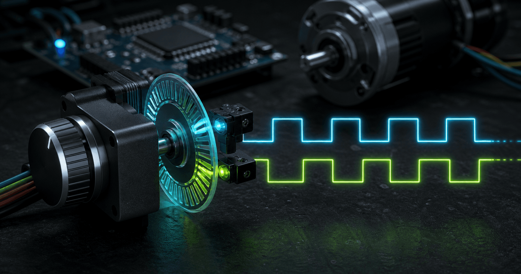
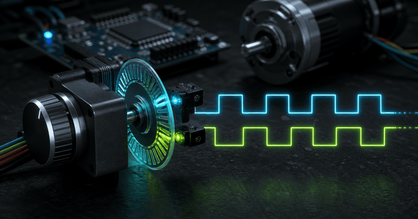
A rotary encoder produces pulses as a shaft turns. Incremental encoders do not know absolute position after power-up unless the system homes itself. Instead, the controller counts steps forward and backward from a known starting point. This makes them ideal for knobs, wheel odometry, and motor speed feedback.
Quadrature A and B Signals
Two channels are offset by 90 electrical degrees. If channel A leads channel B, the shaft is moving one direction. If B leads A, it is moving the other direction. By observing both rising and falling edges, software can get up to four counts per physical cycle.
Debouncing Mechanical Encoders
Mechanical encoders use contacts, and contacts bounce. Without debouncing, one click can appear as several fast pulses. Debouncing can be done in hardware with RC filters and Schmitt triggers, or in software by rejecting transitions that violate the expected quadrature state sequence.
Speed and Position Feedback
For motors, an encoder turns rotation into measurable speed and position. Speed comes from counts per time interval. Position comes from accumulated counts. Closed-loop systems use that feedback with PID control to correct error between target and actual motion.
Parts and Modules Availability in India
For student labs and prototype builds in India, look for the exact voltage rating, interface level, package type, and module quality before buying. SP Road in Bangalore, Lamington Road in Mumbai, Lajpat Rai Market in Delhi, Ritchie Street in Chennai, Koti in Hyderabad, Budhwar Peth in Pune, and Chandni Chowk Market in Kolkata commonly stock beginner-friendly modules and passives.
Frequently Asked Questions
What does a rotary encoder do?
A rotary encoder converts shaft movement into pulses. By reading the pulse sequence, a controller can infer direction, speed, and relative position.
Why do rotary encoders matter in electronics?
It matters because small interface decisions can change accuracy, reliability, safety, and debugging time. Understanding the fundamentals helps you choose values, modules, and wiring methods intentionally.
What is the most common rotary encoder mistake?
The most common mistake is treating the circuit as ideal. Real components have limits such as input impedance, noise, timing, voltage ratings, heating, drift, or contact behavior.
Can beginners use this in Arduino projects?
Yes. Start with a low-voltage breadboard setup, verify ratings, use conservative resistor values or modules, and test one signal at a time before connecting expensive boards or high-power loads.
Conclusion
How Rotary Encoders Work becomes much easier when you separate the ideal idea from the physical limits. Use the specs above, test with conservative values, and connect this topic with related Volt X guides before scaling a prototype into a finished build.