📡 Two-Arduino Serial Communication
Send real sensor data wirelessly between two Arduinos via UART serial — your first hands-on hardware communication protocol.
Overview
UART (Universal Asynchronous Receiver-Transmitter) is the simplest and most universal serial communication protocol. Understanding it unlocks GPS, Bluetooth, GSM, and virtually every wireless module you'll ever use in electronics.
Technical Insight: UART transmits data bit-by-bit at a fixed baud rate (bits per second). At 9600 baud, each bit takes ~104µs. A start bit, 8 data bits, and a stop bit form one byte frame. Both devices must agree on the same baud rate — no clock line needed. Arduino's SoftwareSerial library lets you emulate UART on any two digital pins, freeing the hardware UART for debugging.
In simple terms: One Arduino (the Transmitter) reads a sensor and packs the reading into a short text message, then sends it as a stream of HIGH/LOW voltage pulses. The second Arduino (the Receiver) reconstructs those pulses back into the original text and displays it.
What you'll learn: UART protocol basics (start/stop bits, baud rate), SoftwareSerial.h usage, cross-device communication, data framing with newline delimiters, and debugging multi-device systems.
Estimated time: 45-60 minutes. Difficulty: ⭐⭐⭐ Intermediate — introduces multi-device hardware systems.
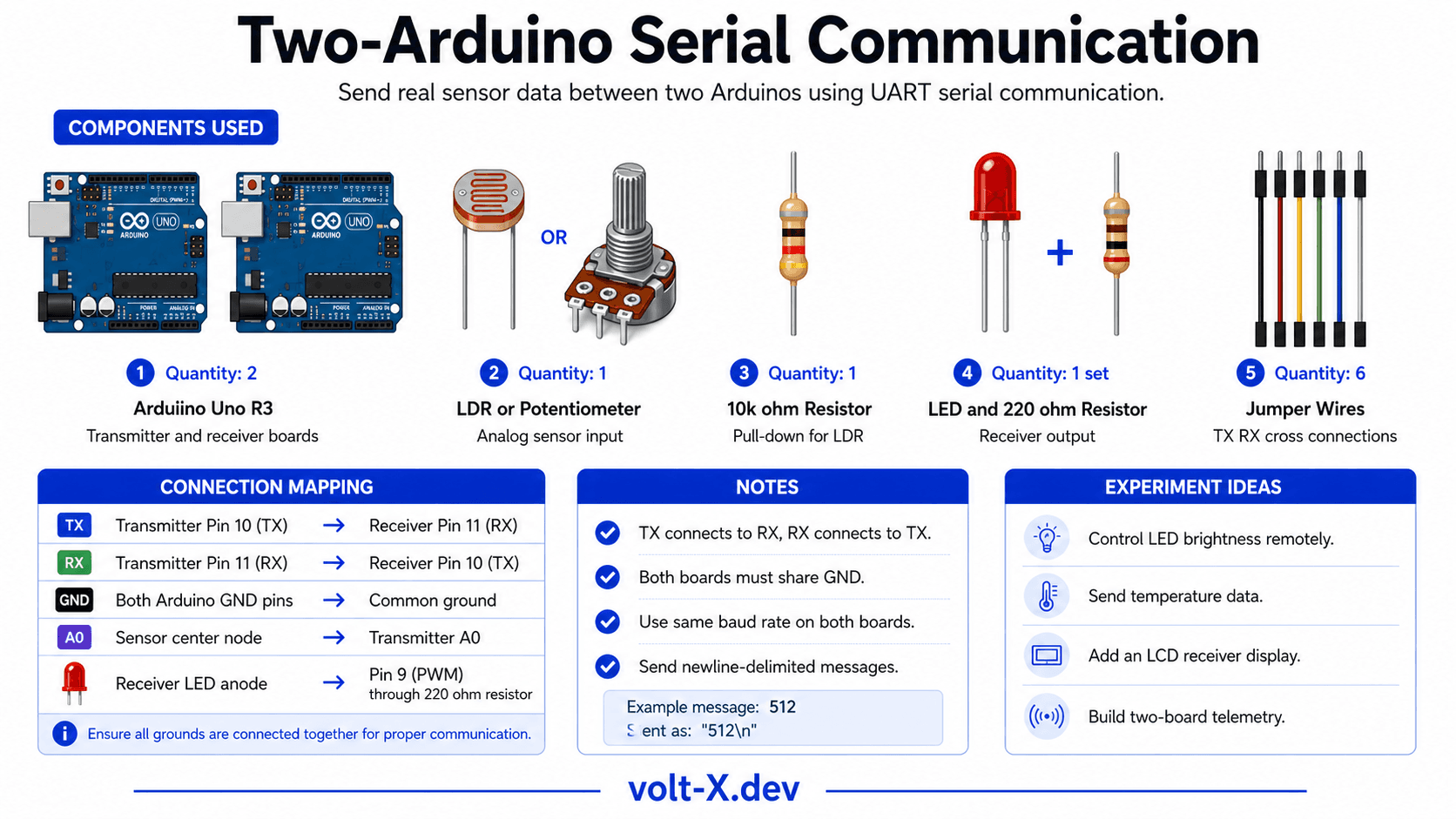
Components Needed
| Component | Specification | Qty | Notes |
|---|---|---|---|
| Arduino Uno R3 | 5V | 2 | One Transmitter, one Receiver |
| LDR / Potentiometer | Analog sensor | 1 | For Transmitter to read |
| 10kΩ Resistor | Pull-down for LDR | 1 | |
| LED + 220Ω Resistor | 1 | Controlled by Receiver | |
| 16x2 LCD with I2C | Optional | 1 | Shows received data on Receiver |
| Jumper Wires | M-M | 6 | TX/RX cross-connection |
Component Pin Mapping
Step-by-Step Tutorial
Cross-Connect TX and RX
Wire the Sensor on Transmitter
Upload Transmitter Sketch
Upload Receiver Sketch
Observe Live Data
Arduino Code
// ====== TRANSMITTER ARDUINO CODE — Volt X ======
// Upload this to Arduino #1 (has the sensor)
#include <SoftwareSerial.h>

SoftwareSerial mySerial(11, 10); // RX=11, TX=10
const int SENSOR_PIN = A0;

void setup() {
  mySerial.begin(9600);
  Serial.begin(9600);
  Serial.println("TRANSMITTER Ready");
}

void loop() {
  int sensorVal = analogRead(SENSOR_PIN);
  int mapped    = map(sensorVal, 0, 1023, 0, 100); // 0-100%

  mySerial.print("DATA:");
  mySerial.println(mapped);

  Serial.print("Sent: "); Serial.println(mapped);
  delay(500);
}

// ====== RECEIVER ARDUINO CODE — Volt X ======Reviews & Ratings
Sign in to leave a review
Loading reviews...