🔬 Transistor NPN Switch
Master the most fundamental component in electronics — use a BC547 NPN transistor to switch a motor or relay from a weak microcontroller signal.
Overview
The transistor is arguably the most important invention of the 20th century. A single BC547 NPN transistor can control 100mA of collector current with just 1mA of base current — a current gain (hFE) of 100 or more.
Technical Insight: In saturation mode (switch fully ON), the base-emitter junction is forward-biased at ~0.7V, and the collector-emitter drop is only ~0.2V. By calculating the base resistor: R_B = (V_in − 0.7) / I_B, where I_B = I_C / hFE, we ensure the transistor is fully saturated and acting as a closed switch — not a linear amplifier.
In simple terms: The transistor is a water tap — a tiny signal at the base 'handle' controls a large flow from collector to emitter. Arduino is too weak to power a motor directly, but with a transistor between them, the Arduino controls the motor with no risk.
What you'll learn: BJT operation modes (cutoff, saturation, active), base resistor calculation, flyback diode need for inductive loads, and why transistors replaced mechanical relays.
Estimated time: 30-40 minutes. Difficulty: ⭐⭐ Easy — essential electronics theory brought to life.
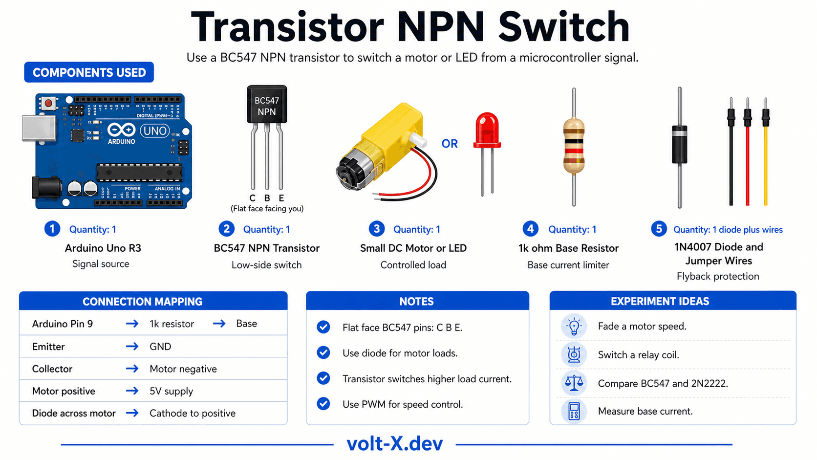
Components Needed
| Component | Specification | Qty | Notes |
|---|---|---|---|
| Arduino Uno R3 | 5V | 1 | |
| BC547 NPN Transistor | hFE ≥ 100, 45V, 100mA | 1 | Or 2N2222 equivalent |
| Small DC Motor / LED | 5V, <100mA | 1 | The controlled load |
| Resistor (base) | 1kΩ | 1 | Controls base current |
| 1N4007 Diode | Flyback protection | 1 | Needed for motor loads |
| Breadboard + Wires | Half-size | 1 |
Component Pin Mapping
Step-by-Step Tutorial
Identify Transistor Pins
Wire the Circuit
Upload Blink Code
Measure Base Current
PWM Speed Control
digitalWrite to analogWrite and vary speed from 0–255.Arduino Code
// Transistor NPN Switch — Volt X
// BC547 switching a DC motor via Arduino PWM

const int CTRL_PIN = 9; // Connected to base via 1kΩ resistor

void setup() {
  pinMode(CTRL_PIN, OUTPUT);
  Serial.begin(9600);
}

void loop() {
  // === Full ON (digital) ===
  Serial.println("Motor ON  (full speed)");
  digitalWrite(CTRL_PIN, HIGH);
  delay(2000);

  // === Full OFF ===
  Serial.println("Motor OFF");
  digitalWrite(CTRL_PIN, LOW);
  delay(1000);

  // === Half Speed via PWM ===
  Serial.println("Motor HALF speed (PWM 128)");
  analogWrite(CTRL_PIN, 128);
delay(2000);Reviews & Ratings
Sign in to leave a review
Loading reviews...