🎙️ Sound Level Meter
Visualize ambient noise with a 10-LED VU meter driven by a microphone module — your first audio electronics project.
Overview
Sound is pressure waves that a microphone converts into electrical voltage. An electret microphone module outputs an analog voltage proportional to sound pressure. Arduino samples this and drives a visual LED bar graph — like a professional VU (Volume Unit) meter.
Technical Insight: The KY-038 microphone module uses an electret capsule paired with an LM393 comparator. The analog output swings around 2.5V at silence, going higher with loud sounds. We sample this signal multiple times per loop, find the peak deviation from the baseline, and map it to 0–10 LEDs.
In simple terms: The microphone 'sneezes' a tiny voltage when it hears sound. We repeatedly check that voltage, find how far it jumped, and light up more LEDs the louder it gets.
What you'll learn: Electret microphone interfacing, peak-detection sampling over a time window, analog value mapping, multi-LED array control, and audio signal basics.
Estimated time: 40-55 minutes. Difficulty: ⭐⭐ Easy.
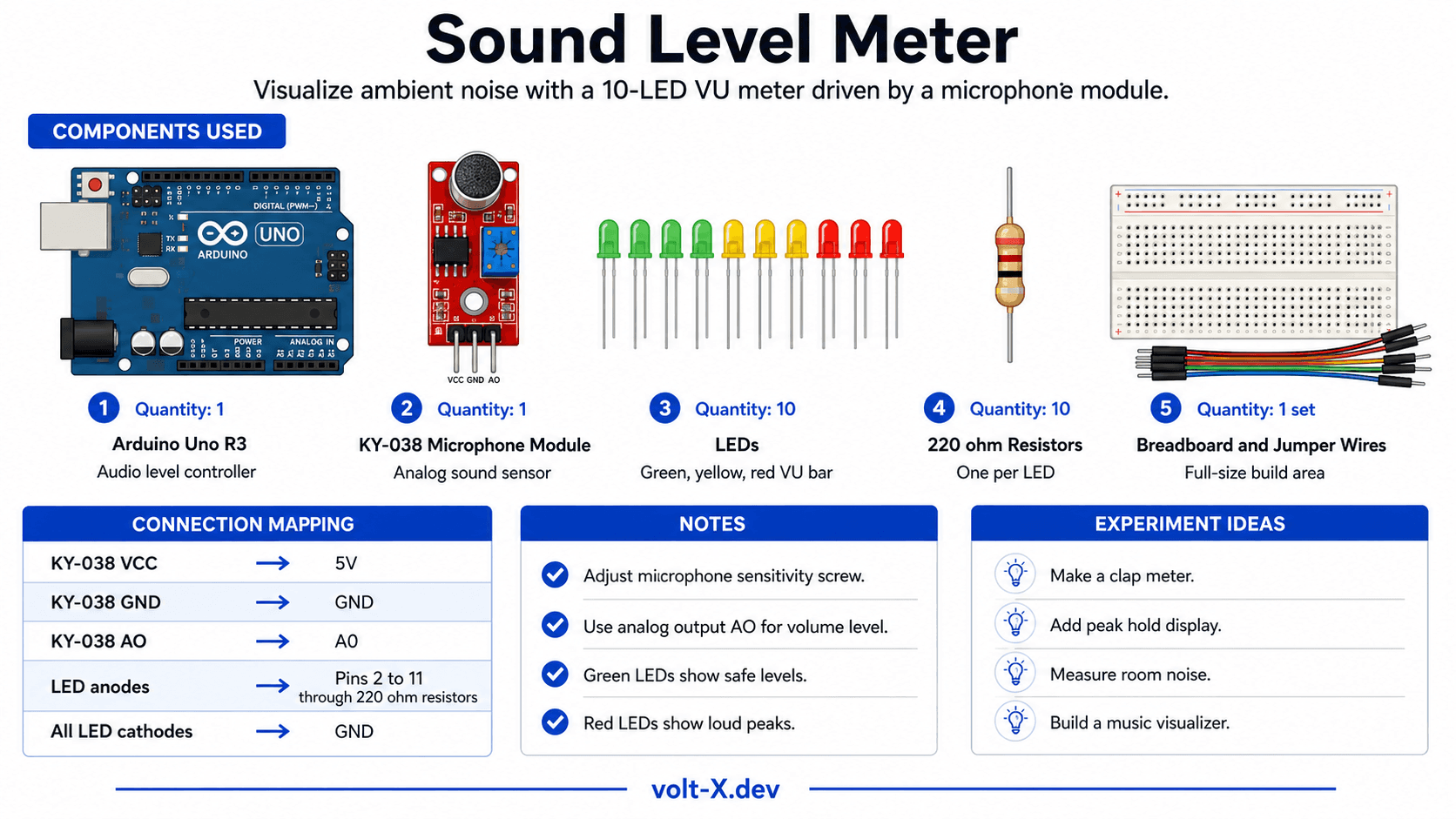
Components Needed
| Component | Specification | Qty | Notes |
|---|---|---|---|
| Arduino Uno R3 | 5V | 1 | |
| KY-038 Microphone Module | Electret with LM393 | 1 | Analog output type |
| LEDs (assorted colors) | 5mm, Red/Yellow/Green | 10 | 5G + 3Y + 2R for VU effect |
| Resistors | 220Ω | 10 | One per LED |
| Breadboard + Wires | Full-size | 1 |
Component Pin Mapping
Step-by-Step Tutorial
Wire the Microphone
Set Up LED Array
Upload the Code
Calibrate Sensitivity
Color Code Your LEDs
Arduino Code
// Sound Level Meter (VU Meter) — Volt X
// KY-038 mic on A0, 10 LEDs on pins 2-11

const int MIC_PIN    = A0;
const int NUM_LEDS   = 10;
const int LED_PINS[] = {2,3,4,5,6,7,8,9,10,11};
const int SAMPLE_MS  = 50;  // Sampling window in ms
const int BASELINE   = 512; // Mid-point for 5V supply

void setup() {
  for (int i = 0; i < NUM_LEDS; i++)
    pinMode(LED_PINS[i], OUTPUT);
  Serial.begin(9600);
}

int samplePeak() {
  unsigned long start = millis();
  int peak = 0;
  while (millis() - start < SAMPLE_MS) {
    int val = abs(analogRead(MIC_PIN) - BASELINE);
    if (val > peak) peak = val;
  }
  return peak;
}
Reviews & Ratings
Sign in to leave a review
Loading reviews...