🔢 Rotary Encoder Counter
Precisely count clockwise and counter-clockwise rotations — the foundation of all robot wheel odometry and CNC axis positioning.
Overview
A rotary encoder converts physical rotation into digital pulses. Unlike a potentiometer (which has a fixed range), an encoder has unlimited range and can count both direction and precise steps — making it ideal for motor position feedback in robotics.
Technical Insight: A mechanical rotary encoder generates two phase-shifted square waves (channels A and B). When turning clockwise, A leads B by 90°. Counter-clockwise, B leads A. By detecting the state of B when A makes a falling edge, we determine direction with a single interrupt service routine — no polling needed.
In simple terms: The encoder clicks like a gear. Each click fires an interrupt. By checking which signal came first, we add or subtract one from the count — like counting heartbeats with an ECG.
What you'll learn: Hardware interrupt usage (attachInterrupt), quadrature decoding logic, volatile variables for ISR safety, 7-segment display control, and encoder applications in robotics.
Estimated time: 40-55 minutes. Difficulty: ⭐⭐⭐ Intermediate — introduces interrupt programming.
Components Needed
| Component | Specification | Qty | Notes |
|---|---|---|---|
| Arduino Uno R3 | 5V | 1 | |
| Rotary Encoder | KY-040 module | 1 | 20 detents per revolution |
| 7-Segment Display | Common Cathode, 1-digit | 1 | Shows count 0–9 |
| Resistors | 220Ω | 7 | One per segment |
| Breadboard + Wires | Full-size | 1 |
Component Pin Mapping
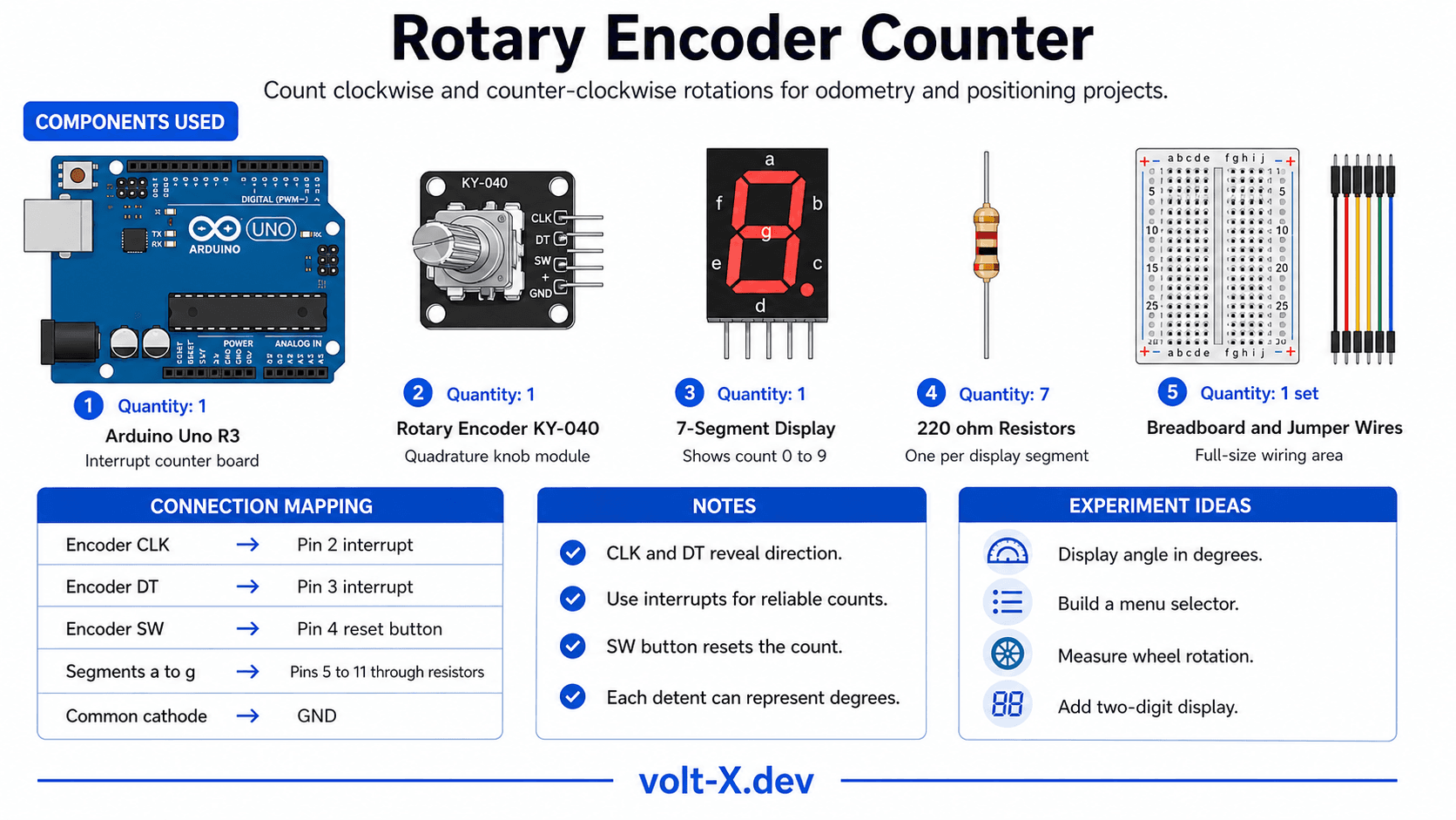
Step-by-Step Tutorial
Wire the Encoder
Wire the 7-Segment
Upload Code
Push Button Reset
Scale to Angle
Arduino Code
// Rotary Encoder Counter — Volt X
// KY-040 on pins 2(CLK) & 3(DT), 7-seg on pins 5-11

const int CLK = 2, DT = 3, SW = 4;
volatile int count = 0;
int lastCLK;

// Segment patterns for digits 0-9 (a,b,c,d,e,f,g)
const byte SEG_PINS[7] = {5,6,7,8,9,10,11};
const byte DIGITS[10][7] = {
  {1,1,1,1,1,1,0}, // 0
  {0,1,1,0,0,0,0}, // 1
  {1,1,0,1,1,0,1}, // 2
  {1,1,1,1,0,0,1}, // 3
  {0,1,1,0,0,1,1}, // 4
  {1,0,1,1,0,1,1}, // 5
  {1,0,1,1,1,1,1}, // 6
  {1,1,1,0,0,0,0}, // 7
  {1,1,1,1,1,1,1}, // 8
  {1,1,1,1,0,1,1}, // 9
};

void showDigit(int n) {
  n = abs(n) % 10;
for (int i = 0; i < 7; i++) digitalWrite(SEG_PINS[i], DIGITS[n][i]);Reviews & Ratings
Sign in to leave a review
Loading reviews...