Humidity Sensor (DHT11)
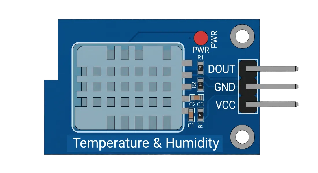
What is DHT11?
The DHT11 is a basic, ultra low-cost digital temperature and humidity sensor. It uses a capacitive humidity sensor and a thermistor to measure the surrounding air, and spits out a digital signal on the data pin.
This sensor is highly favored for its simplicity and affordability, making it the perfect choice for basic environmental data gathering like home automation, weather stations, and soil/climate monitoring projects.
Key Features
Dual Measurement
Simultaneously measures relative humidity and ambient temperature.
Digital Output
Transmits calibrated, single-wire digital signals directly to the microcontroller.
Internal Calibration
Factory calibrated coefficients stored in OTP memory for high accuracy.
Cost-Effective
Extremely affordable component ideal for educational and hobby projects.
Low Power
Consumes minimal current (0.5mA to 2.5mA) during measurement cycles.
Resistive Humidity
Uses a humidity-sensing component and an NTC temperature sensor for stability.
Pin Configuration
VCC
3.3V - 5V Power Supply. Connect to the microcontroller power output pin.
DATA
Single-wire digital data output. Transmits 40-bit data packet (humidity + temp).
NC
Not Connected. Leave floating or unconnected on 4-pin packages.
GND
Ground connection. Connect to the common ground reference of the board.
How It Works
The Science Behind It
The DHT11 uses a Capacitive Humidity Sensor and a Negative Temperature Coefficient (NTC) Thermistor. The humidity-sensing element is a moisture-holding substrate with electrodes on either side. As humidity changes, the substrate absorbs or releases water, changing the capacitance between the electrodes.
An internal IC converts these analog signals into a calibrated digital signal using a proprietary 1-Wire protocol (40-bit data frame), meaning you only need a single data pin to read both temperature and humidity.
Relative Humidity & Data Frame:
Relative Humidity (%) = (Water Vapor Pressure / Saturation Pressure) × 100

40-Bit Data: 8bit Integral RH + 8bit Decimal RH + 8bit Integral Temp + 8bit Decimal Temp + 8bit Checksum
Wiring Tips & Best Practices
Pull-up Resistor
Add a 5kΩ - 10kΩ pull-up resistor between the DATA and VCC line to ensure stable data transmission.
Sampling Interval
DHT11 requires at least 1-2 seconds between read cycles. Polling faster will result in old or inaccurate data.
Voltage Match
Can run on 3.3V or 5V. Align the voltage with your microcontroller's logic level (e.g., 3.3V for ESP32).
Avoid Condensation
Do not expose the sensor to direct water or condensation, as it will saturate and damage the humidity element.
Placement
Keep the sensor away from direct heat sources (like microcontrollers or voltage regulators) for accurate readings.
Wire Length
Keep the signal wire short. For wires longer than 20 meters, use a lower pull-up resistor value (e.g., 5.1kΩ).