Arduino Nano V3 & ATmega328P
What is Arduino Nano V3 & ATmega328P?
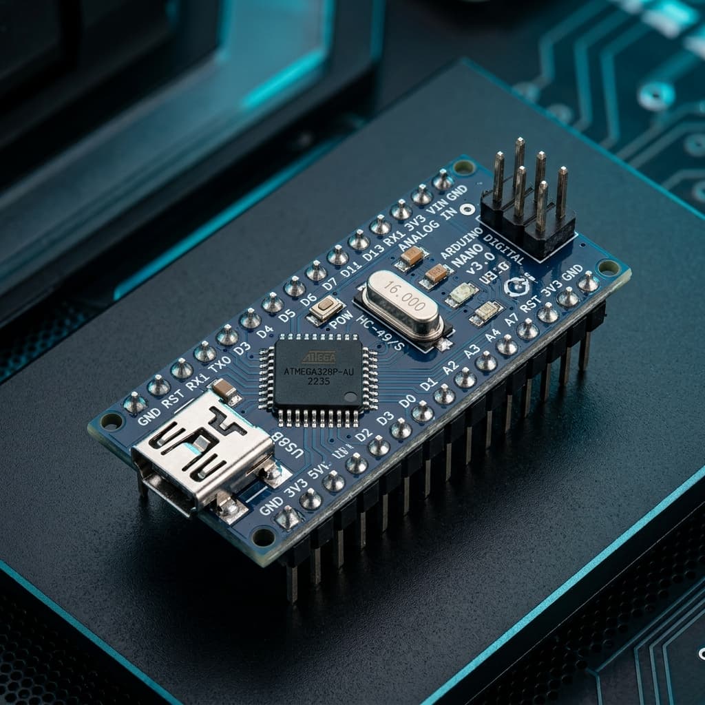
The Arduino Nano V3 is a compact, breadboard-friendly microcontroller board based on the Microchip ATmega328P 8-bit AVR processor. Operating at 16 MHz with 5V logic, it delivers the full processing power, memory, and software library compatibility of the classic Arduino Uno in a fraction of the physical footprint.
Unlike the Uno, the Nano features dual-row header pins spaced precisely at standard 0.1-inch (2.54 mm) pitch, allowing it to plug directly into solderless breadboards without jumper clutter. Furthermore, because it uses the 32-pin TQFP surface-mount package rather than the Uno’s 28-pin DIP package, the Nano exposes two additional 10-bit analog input channels (A6 and A7).
Technical Specifications
Recommended Applications & Industry Uses
Breadboard Prototyping & Education
Standard 0.1-inch header pitch fits cleanly across breadboard power rails, making it ideal for electronics labs and classroom exercises.
Compact Robotics & Mechatronics
Controls line-following robots, dual H-bridge motor drivers, and ultrasonic obstacle avoidance in miniature vehicle chassis.
Custom MIDI Controllers & Macropads
Reads banks of analog potentiometers and mechanical switches to emit MIDI notes or control synthesizers and stage lighting.
Multi-Sensor Data Loggers
Utilizes 8 analog input channels (including dedicated A6 and A7) to monitor environmental, soil, and battery parameters simultaneously.
Key Features & Architectural Highlights
Breadboard-Friendly Design
0.1" DIP SpacingPlugs directly into standard solderless breadboards. Eliminates bulky shields and wire tangles, drastically accelerating prototype iteration.
Extra Analog Inputs (A0–A7)
8 ADC ChannelsExposes 8 analog input channels (A0 to A7)—two more than the Arduino Uno—making it superior for multi-sensor measurement arrays.
Microchip ATmega328P
16 MHz AVR CoreProven 8-bit RISC architecture with single-cycle execution of most instructions. Compatible with 100% of standard Arduino libraries and examples.
Flexible Power Options
7V - 12V VIN RangePower via USB cable, an unregulated 7V–12V external power supply connected to VIN, or a regulated 5V power source connected to the 5V pin.
5V Tolerant I/O Lines
Rugged 5V LogicOperates natively at 5V logic with 20mA output drive capacity per pin, allowing direct connection to standard hobbyist sensors and relays.
Standard Memory Matrix
32KB Flash / 2KB SRAMIncludes 32 KB Flash memory (2 KB used by bootloader), 2 KB SRAM for variables, and 1 KB EEPROM for non-volatile parameter storage.
Pin Configuration & Peripheral Layout
Digital GPIO Pins (D0 - D13)
14 digital I/O pins operating at 5V logic with up to 20mA current capability per pin.
- Pins D3, D5, D6, D9, D10, D11 provide 8-bit hardware PWM output (analogWrite)
- Pins D2 and D3 support hardware external interrupts (INT0 and INT1)
- Pin D13 drives the onboard user LED via an internal series resistor
Analog Inputs (A0 - A7)
8 dedicated 10-bit successive approximation ADC channels converting voltages from 0 to 5V.
- Converts 0–5V inputs into discrete integers from 0 to 1023 (4.88 mV per step)
- Pins A4 (SDA) and A5 (SCL) also host the hardware I2C bus
- Pins A6 and A7 are pure analog inputs (cannot be configured as digital outputs)
Power & Communication Rails
Dedicated power regulation pins, hardware serial buses, and system reset lines.
- VIN pin accepts 7V to 12V unregulated DC input from battery packs or wall adapters
- 5V pin outputs regulated 5V (or accepts regulated 5V when USB is disconnected)
- 3V3 pin outputs up to 50mA from the onboard FTDI / CH340 regulator
Communication Protocols
Hardware UART
D0 (RX) & D1 (TX)
Full-duplex serial communication up to 115200 baud connected to the USB-to-UART chip and PC Serial Monitor.
I2C Bus (TWI)
A4 (SDA) & A5 (SCL)
Two-wire synchronous serial interface supporting multiple sensors and OLED displays on a shared 2-wire bus.
SPI Interface
D10 (SS), D11 (MOSI), D12 (MISO), D13 (SCK)
High-speed synchronous serial peripheral interface running up to 8 MHz for SD card modules, RF radios, and shift registers.
PWM Waveforms
D3, D5, D6, D9, D10, D11
Hardware pulse-width modulation operating at 490 Hz (D3, D9, D10, D11) and 980 Hz (D5, D6) for motor speed and LED dimming.
External Interrupts
D2 (INT0) & D3 (INT1)
Triggers ISR callback functions instantly on LOW, CHANGE, RISING, or FALLING signal transitions with zero polling overhead.
ICSP Programming
MISO, MOSI, SCK, RESET, VCC, GND
In-circuit serial programming header for direct ISP programmers like USBasp, AVRISP mkII, or another Arduino.
Advanced Topics & Expert Knowledge
Hardware Timer PWM Registers
Bypass analogWrite() to configure Timer0, Timer1, or Timer2 directly for custom frequencies up to 62.5 kHz for silent motor drives.
Pro tip: Timer0 controls millis() and delay(); modifying Timer0 alters Arduino system timing functions.
Pin Change Interrupts (PCINT)
All 22 digital and analog pins can trigger Pin Change Interrupts across 3 port groups (PCINT0, PCINT1, PCINT2) for rotary encoders.
Pro tip: Use PCINT when external interrupt pins D2 and D3 are already occupied by high-priority sensors.
AVR Low Power Sleep Modes
Enter Power-down mode using avr/sleep.h to drop current consumption from 15mA down to under 50µA on battery-powered projects.
Pro tip: Disconnect the power LED resistor and remove the USB-to-UART chip on clones for true sub-100µA battery runtimes.
Direct Port Register I/O
Manipulate PORTB, PORTC, and PORTD directly to toggle pins in 62.5 nanoseconds (single clock cycle)—over 40x faster than digitalWrite().
Pro tip: Direct port writes allow writing an entire 8-bit parallel bus simultaneously in a single CPU cycle.
Internal EEPROM Storage
Store calibration offsets, Wi-Fi credentials, and system states in 1024 bytes of non-volatile EEPROM with 100,000 write cycle endurance.
Pro tip: Use EEPROM.update() instead of EEPROM.write() to prevent unnecessary cell wear when data has not changed.
Watchdog Timer (WDT)
Prevent system lockups in remote deployments. If firmware hangs in an infinite loop, the internal 128 kHz watchdog resets the MCU.
Pro tip: Ensure your bootloader clears MCUSR on startup; older bootloaders can enter infinite reset loops if WDT triggers.
Recommended Applications & Industry Uses
Breadboard Prototyping & Education
Standard 0.1-inch header pitch fits cleanly across breadboard power rails, making it ideal for electronics labs and classroom exercises.
Compact Robotics & Mechatronics
Controls line-following robots, dual H-bridge motor drivers, and ultrasonic obstacle avoidance in miniature vehicle chassis.
Custom MIDI Controllers & Macropads
Reads banks of analog potentiometers and mechanical switches to emit MIDI notes or control synthesizers and stage lighting.
Multi-Sensor Data Loggers
Utilizes 8 analog input channels (including dedicated A6 and A7) to monitor environmental, soil, and battery parameters simultaneously.
Programming on Arduino Nano V3 & ATmega328P
📚 Official Citations & Technical References
To ensure the absolute accuracy and reliability of this guide, all specifications, pinouts, and register settings have been cross-verified with official manufacturer documentation:
Related Resources
Frequently Asked Questions
What is the main difference between Arduino Uno and Arduino Nano?
Both boards share the same ATmega328P 16 MHz microcontroller and 32 KB Flash. The Nano is compact, fits directly into breadboards, and exposes 8 analog pins (A0–A7), compared to 6 on the Uno.
How do I fix the "avrdude: stk500_recv()" upload error on Arduino Nano?
In the Arduino IDE, go to Tools > Processor and switch between "ATmega328P" and "ATmega328P (Old Bootloader)". Most affordable clone Nano boards use the Old Bootloader setting.
Why does my computer not recognize the Arduino Nano clone?
Most clone Nano boards use the WCH CH340 or FTDI USB-to-UART chip instead of an ATmega16U2. Download and install the CH340 driver to allow Windows and macOS to recognize the COM port.